Radio frequency power detection circuit

A technology of radio frequency power and detection circuit, which is applied in the direction of electric power measurement through current/voltage, which can solve the problems of poor detection accuracy, many error changes, and high current consumption.

Active Publication Date: 2021-06-18
CHENGDU UNIV OF INFORMATION TECH
View PDF13 Cites 4 Cited by
  • Summary
  • Abstract
  • Description
  • Claims
  • Application Information

AI Technical Summary

Problems solved by technology

[0002] The traditional transmission power detection circuit such as Figure 4 As shown, after the output signal of the RF amplifier passes through the power divider, a part of the signal is amplified through the matching network input logarithmic amplifier to realize the square of the signal amplitude, and then the amplitude of the output signal of the logarithmic amplifier is obtained through the ballast and low-pass filter. In this way, in order to achieve higher line

Method used


Image

  • Radio frequency power detection circuit
  • Radio frequency power detection circuit
  • Radio frequency power detection circuit

Examples


Embodiment Construction

[0030] The specific embodiments of the present invention are described below so that those skilled in the art can understand the present invention, but it should be clear that the present invention is not limited to the scope of the specific embodiments. For those of ordinary skill in the art, as long as various changes Within the spirit and scope of the present invention defined and determined by the appended claims, these changes are obvious, and all inventions and creations using the concept of the present invention are included in the protection list.

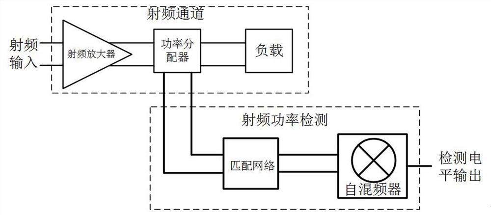
[0031] The traditional transmission power detection circuit such as Figure 4 As shown, after the output signal of the RF amplifier passes through the power divider, a part of the signal is amplified through the matching network input logarithmic amplifier to realize the square of the signal amplitude, and then the amplitude of the output signal of the logarithmic amplifier is obtained through the ballast and low-pass filter....


PUM


Abstract

The invention discloses a radio frequency power detection circuit which comprises a radio frequency channel and a radio frequency power detection channel. The radio frequency channel comprises a radio frequency amplifier, a radio frequency power divider and a load, the input end of the radio frequency amplifier is connected to radio frequency input, the output end of the radio frequency amplifier is connected to the radio frequency power divider, one output of the radio frequency power divider is connected to the load, and the other output is connected to the radio frequency power detection channel; and the radio frequency power detection channel comprises a matching network and a self-mixer, the input end of the matching network is connected to the output end of the radio frequency power divider, the output end of the matching network is connected to the self-mixer, and the self-mixer outputs a detection level. The radio frequency power detection circuit has the advantages that the structure is simple, the power consumption is low, the problems that in a conventional method, in order to realize the high-linearity power detection, number of stages of a logarithmic amplifier needs to be increased, and the ballast needs to carry out ballasting on the output of each stage of logarithmic amplifier at the same time are solved, at the same time, the problem that more errors are introduced due to complex circuits in a traditional mode is solved, and the detection precision is improved.

Description

technical field [0001] The invention relates to the field of integrated circuits, in particular to a radio frequency power detection circuit. Background technique [0002] The traditional transmission power detection circuit such as Figure 4 As shown, after the output signal of the RF amplifier passes through the power divider, a part of the signal is amplified through the matching network input logarithmic amplifier to realize the square of the signal amplitude, and then the amplitude of the output signal of the logarithmic amplifier is obtained through the ballast and low-pass filter. In this way, in order to achieve higher linearity power detection, it is necessary to increase the number of stages of logarithmic amplifiers, and the ballast needs to simultaneously ballast the output of each stage of logarithmic amplifiers, and then filter to obtain and transmit The signal is proportional to the voltage value, the circuit is complicated and the current consumption is high....

Claims


Application Information

Patent Timeline
IPC IPC(8): G01R21/06
CPCG01R21/06
Inventor 丁川姜丹丹陶健叶松李中云马文英
Owner CHENGDU UNIV OF INFORMATION TECH
Why Eureka
Try Eureka