Cooling device
A cooling device and cooling liquid technology, used in semiconductor/solid-state device parts, semiconductor devices, electrical components, etc., can solve the problems of reduced refrigerant flow and cooling efficiency, and achieve the effect of improving cooling performance
- Summary
- Abstract
- Description
- Claims
- Application Information
AI Technical Summary
Problems solved by technology
Method used
Image

Examples
no. 1 Embodiment approach
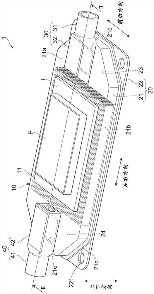
[0032] figure 1 It is a perspective view of the liquid-cooled cooling device 1 of the first embodiment.
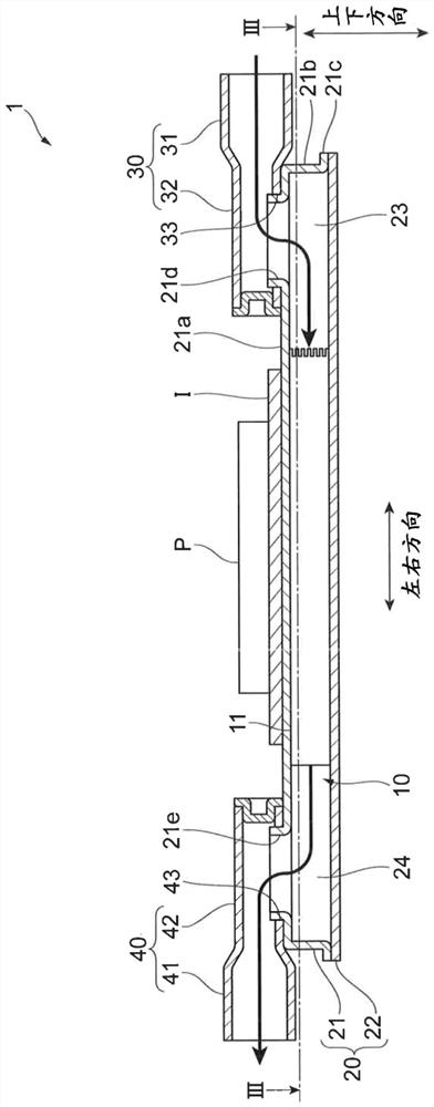
[0033] figure 2 yes figure 1 Sectional view of Part II-II.
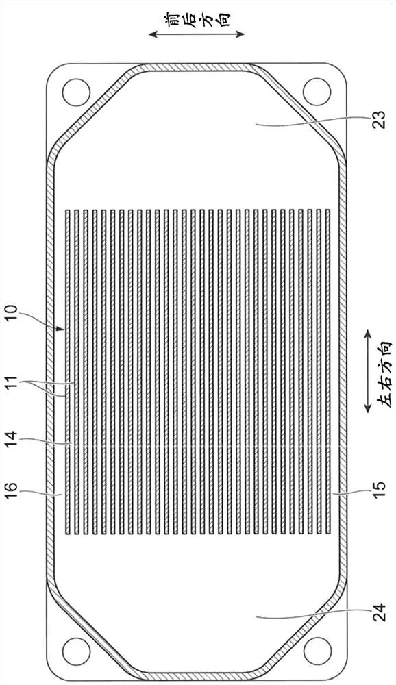
[0034] image 3 yes figure 2 Sectional view of Part III-III.
[0035] A liquid-cooled cooling device 1 according to the embodiment includes a heat sink 10 having a plurality of rectangular fins 11 and a case 20 accommodating the heat sink 10 . In addition, the liquid-cooled cooling device 1 includes an inlet joint 30 through which the cooling liquid flows in from the outside of the case 20 to the inside, and an outlet joint 40 through which the cooling liquid flows out from the inside of the case 20 to the outside. Hereinafter, the long direction of the rectangular fins 11 may be referred to as the left-right direction, the short direction of the fins 11 may be referred to as the up-down direction, and the direction in which the plurality of fins 11 are arranged may be referred to as the front-rear direct...
no. 2 Embodiment approach
[0066] Figure 6 (a) is a perspective view which shows an example of the end part of the inlet joint 30 side in the radiator 50 of 2nd Embodiment.
[0067] Figure 6 (b) is in Figure 6 The figure when viewing the heat sink 50 from the VIb direction of (a).
[0068] The heat sink 50 of the second embodiment differs from the heat sink 10 of the first embodiment in the fins 60 corresponding to the fins 11 . Hereinafter, differences from the heat sink 10 will be described. Components having the same functions in the second embodiment and the first embodiment are denoted by the same reference numerals, and detailed description thereof will be omitted.
[0069] The fins 60 are sequentially formed with recesses 61, 62, 63, 64, 65, Recess 66 . And, if the depths of the recessed portion 61, the recessed portion 62, the recessed portion 63, the recessed portion 64, the recessed portion 65, and the recessed portion 66 are respectively set to b1, b2, b3, b4, b5, and b6, then as F...
no. 3 Embodiment approach
[0073] Figure 7 (a) is a perspective view which shows an example of the end part of the inlet joint 30 side in the radiator 70 of 3rd Embodiment.
[0074] Figure 7 (b) is in Figure 7 The diagram when the heat sink 70 is viewed from the VIIb direction of (a). In other words, Figure 7 (b) is a figure which looked at an example of the end part of the fin 71 by the inlet joint 30 side from the inlet joint 30 side to the outlet joint 40 side.
[0075] The heat sink 70 of the third embodiment differs from the heat sink 10 of the first embodiment in the shape of the fins 71 corresponding to the fins 11 . Hereinafter, differences from the heat sink 10 will be described. Components having the same functions in the third embodiment and the first embodiment are denoted by the same reference numerals, and detailed description thereof will be omitted.
[0076] In the end portion of the fin 71 of the third embodiment, a plurality of recesses 711 are formed at equal intervals in th...
PUM
 Abstract
Description
Claims
Application Information
 - R&D Engineer
- R&D Manager
- IP Professional
- Industry Leading Data Capabilities
- Powerful AI technology
- Patent DNA Extraction
Browse by: Latest US Patents, China's latest patents, Technical Efficacy Thesaurus, Application Domain, Technology Topic.
© 2024 PatSnap. All rights reserved.Legal|Privacy policy|Modern Slavery Act Transparency Statement|Sitemap