Laser radar and automatic driving equipment

A lidar and laser technology, applied in the field of radar, can solve problems such as the influence of ambient light, and achieve the effects of improving ranging performance, improving the ability to fight against ambient light, and improving the signal-to-noise ratio.

Pending Publication Date: 2021-06-18
SUTENG INNOVATION TECH CO LTD
View PDF0 Cites 0 Cited by
  • Summary
  • Abstract
  • Description
  • Claims
  • Application Information

AI Technical Summary

Problems solved by technology

[0004] In view of the above-mentioned defects of the prior art, the main purpose of the embodiments of the present invention is to provide a laser radar and an automatic driving device, which solves the problem that the laser radar in the prior art is easily affected by ambient light

Method used


Image

  • Laser radar and automatic driving equipment
  • Laser radar and automatic driving equipment
  • Laser radar and automatic driving equipment

Examples


Embodiment Construction

[0056] Embodiments of the technical solutions of the present invention will be described in detail below in conjunction with the accompanying drawings. The following examples are only used to illustrate the technical solutions of the present invention more clearly, and therefore are only examples, rather than limiting the protection scope of the present invention.

[0057] It should be noted that, unless otherwise specified, the technical terms or scientific terms used in the present invention shall have the usual meanings understood by those skilled in the art to which the present invention belongs.

[0058] In describing the present invention, it should be understood that the terms "center", "longitudinal", "transverse", "length", "width", "thickness", "upper", "lower", "front", " Back", "Left", "Right", "Vertical", "Horizontal", "Top", "Bottom", "Inner", "Outer", "Clockwise", "Counterclockwise", "Axial", " The orientation or positional relationship indicated by "radial", "...


PUM


Abstract

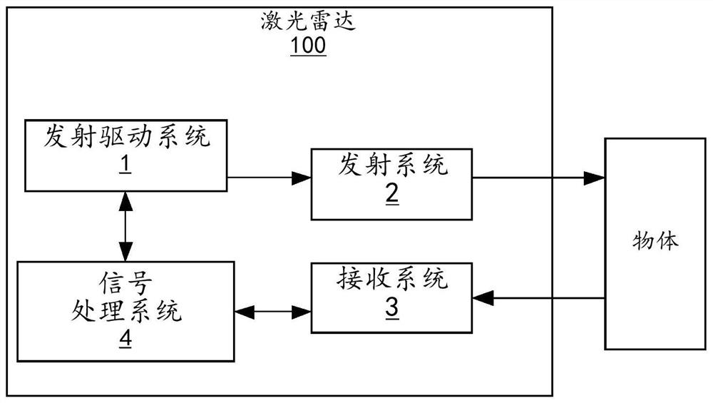
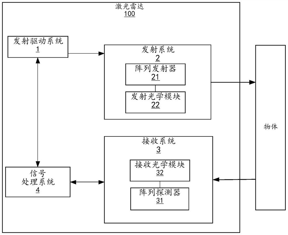
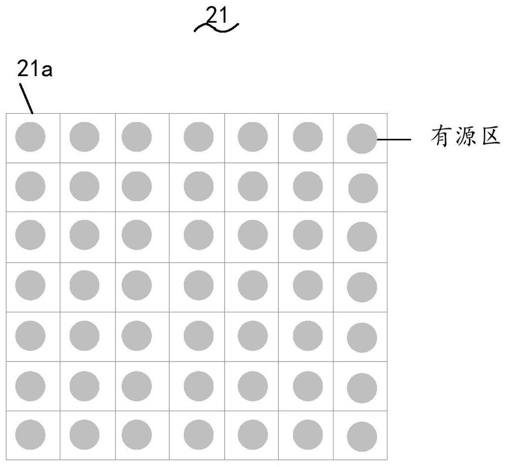
The present invention relates to a laser radar (100) and an automatic driving apparatus. The laser radar comprises an emission driving system (1), an emission system (2), a receiving system (3) and a signal processing system (4). The emitting system (2) comprises a plurality of light emitting units (21a) for emitting emergent laser, and the emitting system (2) is used for starting the light emitting units (21a) according to a first sequence to enable the emergent laser to traverse a detection area in a scanning manner; the receiving system (3) comprises a plurality of detection units (31a) used for receiving the echo laser, and the receiving system (3) is used for starting the selected detection units (31a) to receive the echo laser and detect a detection area scanned by the emergent laser emitted by the light emitting units (21a); the launching driving system (1) is used for driving the launching system (2); the signal processing system (4) is used for calculating the distance information of an object in the detection area based on the emergent laser and the echo laser; the detection unit (31a) comprises a photosensitive area, the ratio of the area of the photosensitive area to the pixel area of the detection unit (31a) is smaller than or equal to 0.5, and the ability of the laser radar (100) to resist ambient light is improved.

Description

technical field [0001] Embodiments of the present invention relate to the technical field of radar, and in particular, to a laser radar and an automatic driving device. Background technique [0002] Lidar is a radar system that uses laser light to detect the position, speed and other characteristics of the target object. Its working principle is that the transmitting system first emits the outgoing laser for detection to the target, and then the receiving system receives the echo laser reflected from the target object. After processing the received echo laser, the relevant information of the target object can be obtained, such as distance, azimuth, height, speed, attitude, and even shape and other parameters. [0003] Area array laser radar refers to the laser radar in which both the transmitting system and the receiving system are area arrays, and there is no rotating scanning structure. For example, the transmitting system is a vertical cavity surface emitting laser array...

Claims


Application Information

Patent Timeline
IPC IPC(8): G01S7/481
CPCG01S7/4815G01S7/4816
Inventor 王超
Owner SUTENG INNOVATION TECH CO LTD
Why Eureka
Try Eureka