Spraying type hydrate continuous reaction device
A technology of reaction device and hydrate, applied in feeding device, chemical/physical/physical-chemical stationary reactor, chemical/physical process, etc., can solve the problems of cumbersome magnetic transmission device, increased energy consumption, high mechanical energy, etc. To achieve the effect of simple structure, maintaining pressure and increasing fluidity
- Summary
- Abstract
- Description
- Claims
- Application Information
AI Technical Summary
Problems solved by technology
Method used
Image

Examples
Embodiment 1
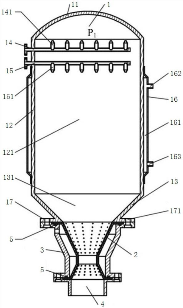
[0022] The main structure of the spray hydrate continuous reaction device involved in this embodiment includes a reactor 1, a fluidized restrictor 2, a fluidized restrictor shell 3 and a pipeline 4; the bottom of the reactor 1 and the fluidized restrictor 2 connection, the periphery of the fluidization restrictor 2 is provided with a fluidization restrictor housing 3, and an air chamber 230 is formed between the fluidization restrictor 2 and the fluidization restrictor housing 3, and the fluidization restrictor 2 The bottom is connected to the pipeline 4; the reaction kettle 1 is composed of a cover 11, an upper cylinder 12 and an upper cone 13 connected in sequence from top to bottom, the inside of the upper cylinder 12 forms a cylindrical cavity 121, and the inside of the upper cone 13 forms a cone Chamber 131, the upper part of the upper cylinder 12 is provided with an air inlet pipe 14 and a liquid inlet pipe 15 parallel to each other, the air inlet pipe 14 is on the top, t...
Embodiment 2
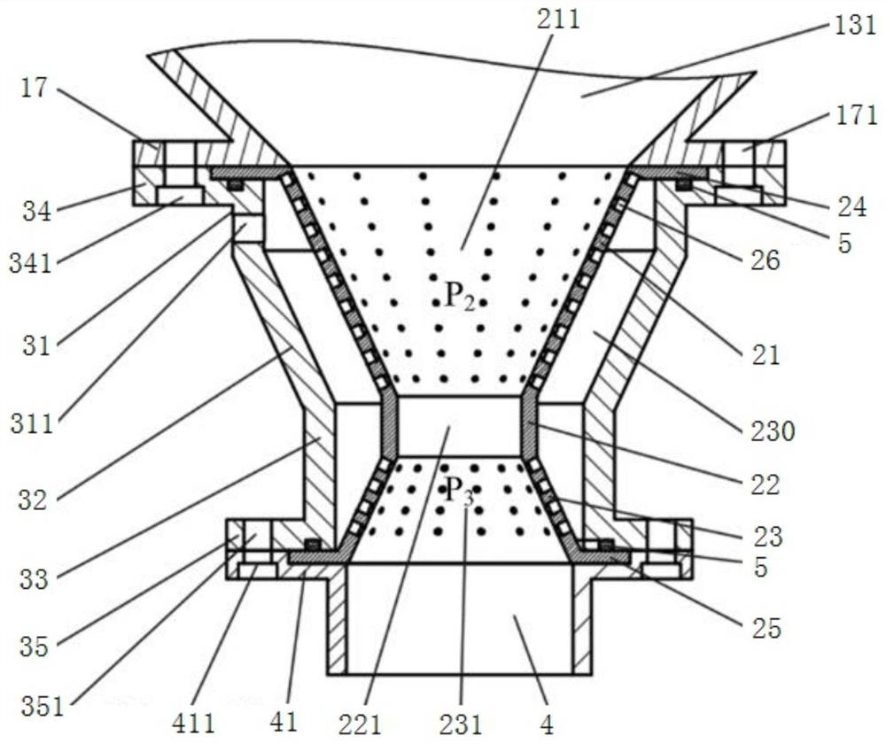
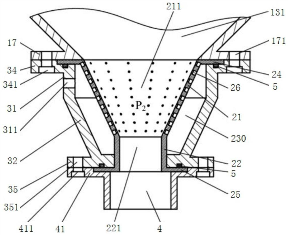
[0025] The main structure of the spray hydrate continuous reaction device involved in this embodiment is different from that of Embodiment 1, the fluidized restrictor 2 and the fluidized restrictor shell 3 are different, and the fluidized restrictor 2 is from top to bottom. The upper porous cone 21 and the throttling cylinder 22 are sequentially connected to form an upper porous cone 21 forming an upper vulcanized cone cavity 211, and the inside of the throttling cylinder 22 forming a throttling cavity 221, and the top circumference of the upper porous cone 21 An upper flange 24 is provided, and a lower flange 25 is provided on the bottom circumference of the throttling cylinder 22. On the upper porous cone 21, several ventilation holes 26 are arranged at equal intervals along the cone generatrix and the circumferential direction, and the ventilation holes 26 are formed by The conical hole 261 and the cylindrical hole 262 are formed; the fluidized restrictor housing 3 is formed...
PUM
 Abstract
Description
Claims
Application Information
 - R&D
- Intellectual Property
- Life Sciences
- Materials
- Tech Scout
- Unparalleled Data Quality
- Higher Quality Content
- 60% Fewer Hallucinations
Browse by: Latest US Patents, China's latest patents, Technical Efficacy Thesaurus, Application Domain, Technology Topic, Popular Technical Reports.
© 2025 PatSnap. All rights reserved.Legal|Privacy policy|Modern Slavery Act Transparency Statement|Sitemap|About US| Contact US: help@patsnap.com