Nutrient soil screening and separating processing machine and processing method thereof
A screening separation and processing machine technology, applied in solid separation, chemical instruments and methods, sieves, etc., can solve the problems of loose nutrient soil, large space occupation, and no large pieces of soil can not crush leaves, etc., to reduce the speed of wear and tear. , the effect of saving space and increasing practicability
- Summary
- Abstract
- Description
- Claims
- Application Information
AI Technical Summary
Problems solved by technology
Method used
Image
Examples
Embodiment 1
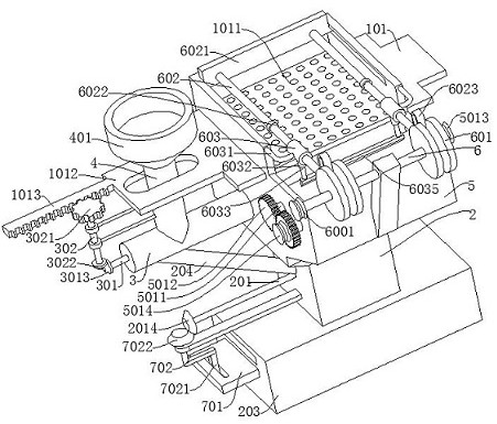
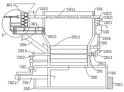
[0035] refer to Figure 1-7 , a nutrient soil screening and separation processing machine, comprising a sieve box 1, a grinding box 5 and a stirring box 2, the grinding box 5 and the stirring box 2 are fixedly connected to the sieve box 1, and the sieve box 1, the grinding box 5 and the stirring box The boxes 2 are connected to each other, the screen box 1 is fixedly connected with a feeding pipe 3 , the feeding pipe 3 is fixedly connected with an extension pipe 4 , and the extension pipe 4 is fixedly connected with a feeding hopper 401 .
Embodiment 2
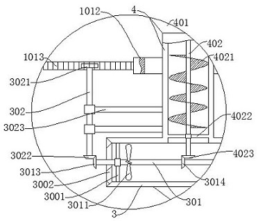
[0037] refer to Figure 1-7 , which is basically the same as that of Example 1, furthermore, a screen frame 101 is slidably connected to the screen box 1, and a screen 1011 is fixedly connected to the screen frame 101, and the screen 1011 removes large pieces of soil, and the screen box 1 is fixed A biaxial motor 102 is connected, the output end of the biaxial motor 102 is fixedly connected with a first drive shaft 1021, a disc 1022 is fixedly connected with the first drive shaft 1021, a cylindrical rod 1023 is fixedly connected with the disc 1022, and a screen frame 101 A hollow bar 1014 is fixedly connected to the top, a cylindrical rod 1023 is slidably connected in the hollow bar 1014, a mounting plate 1012 is fixedly connected to the screen frame 101, a rack 1013 is fixedly connected to the mounting plate 1012, and a first Rotating shaft 301, the first rotating shaft 301 is fixedly connected with the first gear 3013, the blade 3011, the second gear 3014 and the crushing kn...
Embodiment 3
[0039] refer to Figure 1-7 , is basically the same as Embodiment 1, furthermore, the extension pipe 4 is rotatably connected with a one-way rotating rod 302, and the one-way rotating rod 302 only rotates counterclockwise, so that the turbine blade 4021 will not reversely transport the additive, The top of the one-way rotating rod 302 is rotatably connected with a one-way gear 3021, the one-way gear 3021 meshes with the rack 1013, and the bottom of the one-way rotating rod 302 is fixedly connected with a fourth gear 3022, and the fourth gear 3022 meshes with the first gear 3013 , the mounting plate 1012 is provided with a through groove cooperating with the extension pipe 4, the extension pipe 4 is fixedly connected with the first mounting frame 4022, the second rotating shaft 402 is rotatably connected with the first mounting frame 4022, and the feeding pipe 3 is fixedly connected with a The second mounting frame 3001, the first rotating shaft 301 is rotatably connected to th...
PUM
 Abstract
Description
Claims
Application Information
 - R&D
- Intellectual Property
- Life Sciences
- Materials
- Tech Scout
- Unparalleled Data Quality
- Higher Quality Content
- 60% Fewer Hallucinations
Browse by: Latest US Patents, China's latest patents, Technical Efficacy Thesaurus, Application Domain, Technology Topic, Popular Technical Reports.
© 2025 PatSnap. All rights reserved.Legal|Privacy policy|Modern Slavery Act Transparency Statement|Sitemap|About US| Contact US: help@patsnap.com


