Positioning, marking and cutting device for lathe machining and implementation method of positioning, marking and cutting device

A cutting device and lathe processing technology, used in auxiliary devices, metal processing equipment, automatic lathes/semi-automatic lathes, etc., can solve problems such as affecting the production process, wasting production time, errors, etc., to improve work efficiency, cutting Wide-ranging, highly usable effects

Inactive Publication Date: 2021-06-22
定南县沃土园林养护有限公司
View PDF0 Cites 2 Cited by
  • Summary
  • Abstract
  • Description
  • Claims
  • Application Information

AI Technical Summary

Problems solved by technology

[0003] In the process of lathe processing, steel needs to be cut. The cutting devices currently on the market are generally fixed by nuts or screws, which is not only troublesome to fix, but also wastes the time used for production, thus affecting the production process.
If the lathe is not accurately measured during the cutting process, it is easy to have a certain size error, which cannot meet the needs of the factory. Therefore, it is necessary to have a positioning and marking device when the lathe is processed and cut.

Method used


Image

  • Positioning, marking and cutting device for lathe machining and implementation method of positioning, marking and cutting device
  • Positioning, marking and cutting device for lathe machining and implementation method of positioning, marking and cutting device
  • Positioning, marking and cutting device for lathe machining and implementation method of positioning, marking and cutting device

Examples


Embodiment 1

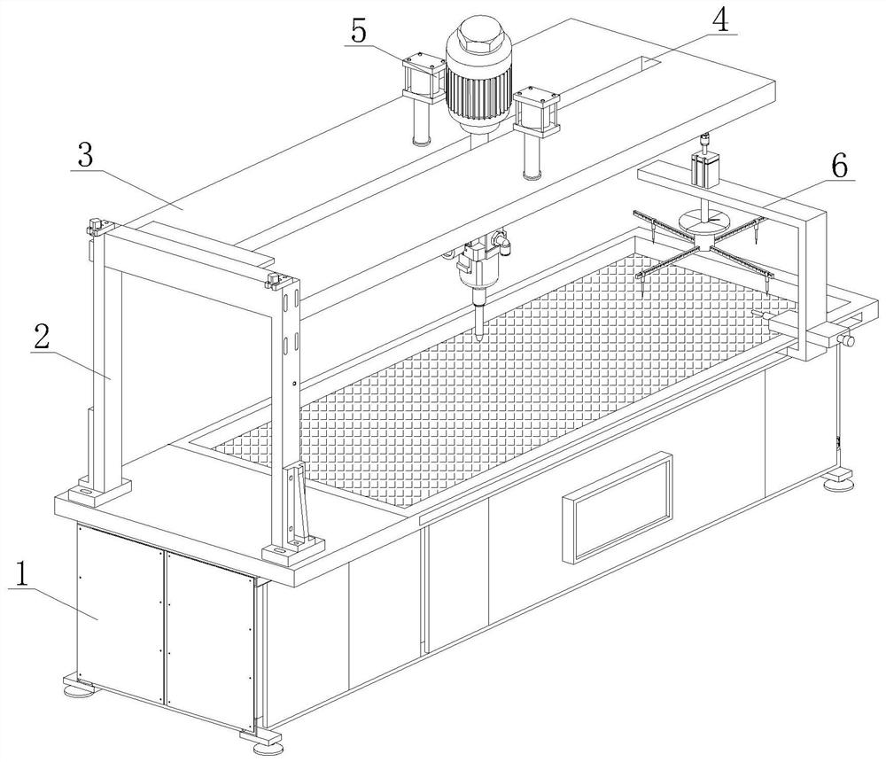
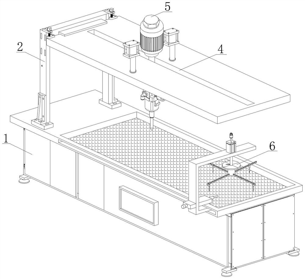
[0037] see Figure 1-2, a kind of positioning marking cutting device for lathe processing, comprising a lathe workbench 1, one side of the upper end surface of the lathe workbench 1 is provided with a support frame group 2, used to support the top plate 3, to prevent the top plate 3 from being insufficiently supported during long-term work Stability causes the falling of the top plate 3 to damage the equipment, so as to improve the stability of equipment installation. The bottom end of the support frame group 2 is welded on the lathe workbench 1, and the top side of the support frame group 2 is vertically connected to the top plate 3, and the top plate 3 There is a chute 4 horizontally in the center of the surface, which is convenient for the cutting mechanism 5 to slide back and forth in the chute 4 to realize multi-directional cutting with a wide cutting range and high practicability of the equipment. The upper and lower end faces and the chute 4 are movably connected with a...

Embodiment 2

[0043] see Figure 1-2 , a kind of positioning marking cutting device for lathe processing, comprising a lathe workbench 1, one side of the upper end surface of the lathe workbench 1 is provided with a support frame group 2, used to support the top plate 3, to prevent the top plate 3 from being insufficiently supported during long-term work Stability causes the falling of the top plate 3 to damage the equipment, so as to improve the stability of equipment installation. The bottom end of the support frame group 2 is welded on the lathe workbench 1, and the top side of the support frame group 2 is vertically connected to the top plate 3, and the top plate 3 There is a chute 4 horizontally in the center of the surface, which is convenient for the cutting mechanism 5 to slide back and forth in the chute 4 to realize multi-directional cutting with a wide cutting range and high practicability of the equipment. The upper and lower end faces and the chute 4 are movably connected with ...

Embodiment approach

[0048] In order to better demonstrate the implementation method of the positioning scribing and cutting device for lathe processing, this embodiment now proposes the implementation method of the positioning and scribing and cutting device for lathe processing, including the following steps:

[0049] Step 1: First, the staff puts the metal object to be processed into the placement table 17 of the cutting support groove 16, and the L-shaped bracket 601 or U-shaped bracket 614 slides in the guide rail 14 through the first slider 602 and the second slider 615 .

[0050] Step 2: Secondly, the cylinder drives the piston rod to move up and down at a constant speed, so that the protractor can measure the precise angle and position on the metal plate.

[0051] Step 3: Finally, mark the measured angle and position with a scribe pen, and control the motor 51 by operating the controller 15 to drive the cutting knife 59 to cut up, down, back and forth.

[0052] To sum up, the positioning ...


PUM


Abstract

The invention discloses a positioning, marking and cutting device for lathe machining and an implementation method of the positioning, marking and cutting device. The positioning, marking and cutting device comprises a lathe workbench, wherein a supporting frame set is arranged on one side of the upper end face of the lathe workbench, the bottom end of the supporting frame set is welded to the lathe workbench, a top plate is vertically connected to one side of the top end of the supporting frame set, and a sliding groove is transversely formed in the center of the surface of the top plate. According to the positioning, marking and cutting device for lathe machining and the implementation method of the positioning, marking and cutting device, the sliding groove is convenient for the front-back sliding of a cutting mechanism in the sliding groove, multi-directional cutting is achieved, the cutting range is wide, high practicability of equipment is achieved, a positioning and marking mechanism is used for marking the surface of a large-size metal steel plate, the steel plate is cut into various shapes according to production requirements, the operation is easy and flexible, the working efficiency is improved. A first air cylinder drives a first piston rod to drive a lifting plate to move up and down at a constant speed, a cutting tool apron is driven to move up and down, and then a motor is started, so that the effect that a cutting tool precisely cuts the metal steel plate is achieved.

Description

technical field [0001] The invention relates to the technical field of lathe processing and cutting devices, in particular to a positioning scribing and cutting device for lathe processing and an implementation method thereof. Background technique [0002] A lathe is a lathe that mainly uses a turning tool to turn a rotating workpiece. It mainly consists of spindle box, exchange gear box, feed box, slide box, tool holder, tailstock, feed rod, lead screw, bed, bed foot and cooling device and other components. Drills, reamers, reamers, taps, dies and knurling tools can also be used for corresponding processing on the lathe. [0003] In the process of lathe processing, steel needs to be cut. The cutting devices currently on the market are generally fixed by nuts or screws, which is not only troublesome to fix, but also wastes the time used for production, thereby affecting the production process. If the lathe is not accurately measured during the cutting process, it is easy t...

Claims


Application Information

Patent Timeline
Patent Type & Authority Applications(China)
IPC IPC(8): B23B11/00B23B25/00B25H7/04B23D79/00
CPCB23B11/00B23B25/00B23D79/00B25H7/04B25H7/045
Inventor 龙晓林
Owner 定南县沃土园林养护有限公司
Why Eureka
Try Eureka