Machining center and processing method for switching clamping, loading and unloading and processing positioning

A processing center and clamp technology, which is applied in the field of wood processing, can solve the problems of the overall efficiency limitation of the wood processing center, the control and guarantee of unfavorable processing accuracy, and the inability to meet the needs of efficient processing, so as to meet the needs of efficient processing and save waiting Time, not easy to shake the effect

Active Publication Date: 2021-11-05
NANXING MACHINERY CO LTD
View PDF9 Cites 0 Cited by
  • Summary
  • Abstract
  • Description
  • Claims
  • Application Information

AI Technical Summary

Problems solved by technology

[0002] With the emergence of microprocessors, the world has entered a new era of numerical control, and the multi-axis control machine tools that can only be realized by computers have risen rapidly, bringing wood processing into an era of automation and intelligence; in the prior art, the general Wood processing centers are all intermittently loaded, processed, and unloaded, and the continuity is not good, resulting in long waiting times. The overall efficiency of wood processing centers is limited, and it is difficult to further improve and cannot meet the needs of efficient processing; for example: the existing technology A kind of wood processing center, which clamps the plate from the loading area to the processing area through the clamp mechanism, and then sends it to the unloading area after processing, and the clamp mechanism returns to the loading area to clamp the next plate to enter the next cycle. This leads to long waiting times in the processing area
[0003] In addition, during feeding and processing, only one clamp mechanism is used to clamp and position the plate, and the positioning reliability is not good, which is not conducive to the control and guarantee of processing accuracy.

Method used


Image

  • Machining center and processing method for switching clamping, loading and unloading and processing positioning
  • Machining center and processing method for switching clamping, loading and unloading and processing positioning
  • Machining center and processing method for switching clamping, loading and unloading and processing positioning

Examples


Embodiment Construction

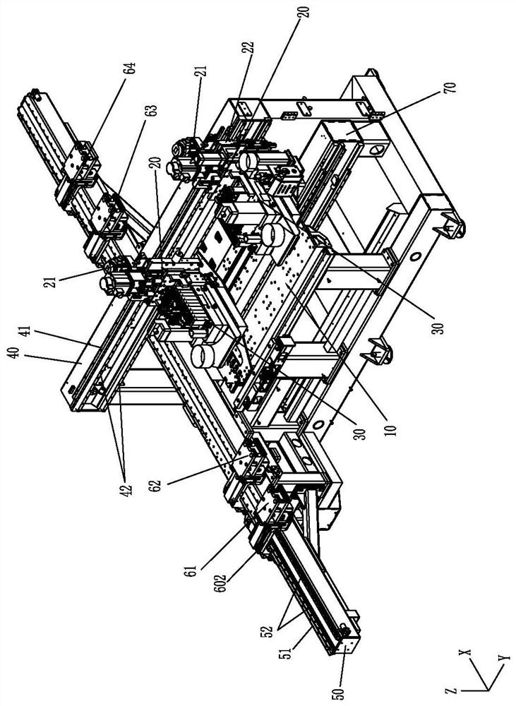
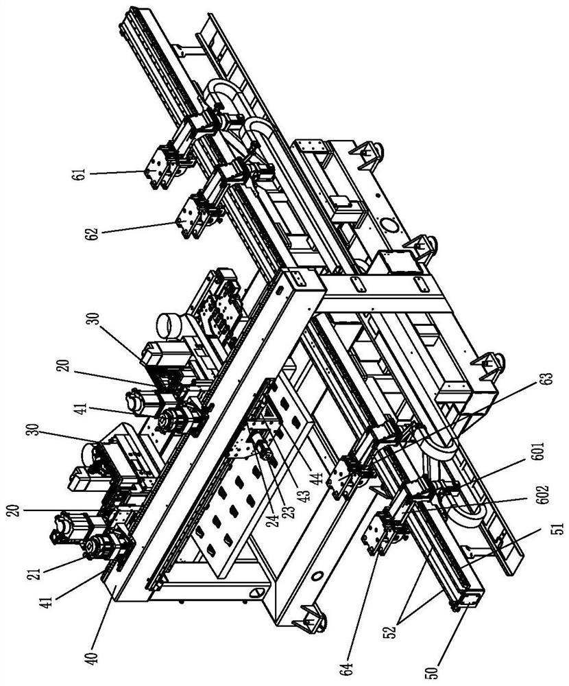
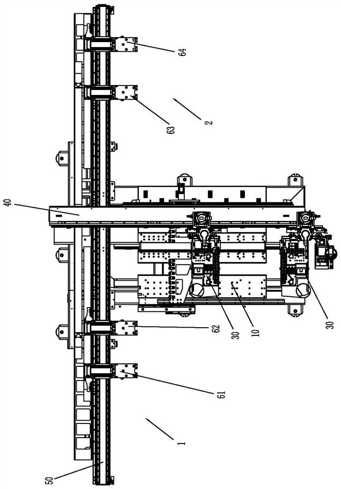
[0056] Please refer to Figure 1 to Figure 6 As shown, it shows the specific structure of the embodiment of the present invention.

[0057] A machining center for switching clamping, loading, unloading, and machining positioning, including a bed, a workbench 10, a beam clamp module, an upper workbench module 20, and an upper machine head 30; wherein:

[0058] The bed includes a Y upward guide rail seat 40, and the Y upward guide rail seat 40 is located above the workbench 10; the upper machine head 30 is installed on the upper workbench module 20, and the Y upward guide rail seat 40 can displacement;

[0059] The beam clamping module includes an X-direction beam 50 and at least four clamping mechanisms that can work independently, which are respectively defined as the first clamping mechanism 61, the second clamping mechanism 62, and the third clamping mechanism from left to right. Mechanism 63, the fourth clamp mechanism 64; the clamp mechanism includes a lower clamp, an up...


PUM


Abstract

The invention discloses a machining center and a machining method for switching, clamping, loading, unloading, and machining positioning, including a bed, a workbench, a beam clamp module, an upper workbench module, and an upper machine head; the upper machine head is a drilling machine head; the bed includes a Y upward guide rail seat, and the Y upward guide rail seat is located above the workbench; the upper machine head is installed on the upper workbench module, and can be displaced along the Y upward guide rail seat; the beam clamp module includes a X The X-direction beam and at least four clamping mechanisms that can work independently are respectively defined as the first to fourth clamping mechanisms from left to right; the X-direction beam, the X-direction rack, and the X-direction rail all extend beyond the left and right sides of the workbench. The left and right sides of the worktable are respectively the loading area and the unloading area. The first clamping mechanism is set corresponding to the loading area, and the second and third clamping mechanisms can be moved back and forth corresponding to the loading area and the working table. The four-clamp mechanism can move back and forth corresponding to the workbench and the blanking area; effectively improving the overall efficiency of the wood processing center.

Description

technical field [0001] The invention relates to the technology in the field of wood processing, in particular to a processing center and a processing method for switching clamping, loading and unloading, and processing positioning. Background technique [0002] With the emergence of microprocessors, the world has entered a new era of numerical control, and the multi-axis control machine tools that can only be realized by computers have risen rapidly, bringing wood processing into an era of automation and intelligence; in the prior art, the general Wood processing centers are all intermittently loaded, processed, and unloaded, and the continuity is not good, resulting in long waiting times. The overall efficiency of wood processing centers is limited, and it is difficult to further improve and cannot meet the needs of efficient processing; for example: the existing technology A kind of wood processing center, which clamps the plate from the loading area to the processing area...

Claims


Application Information

Patent Timeline
Patent Type & Authority Patents(China)
IPC IPC(8): B27C9/04B27C3/04
CPCB27C3/04B27C9/04
Inventor 陶宏建郑永康容华兴
Owner NANXING MACHINERY CO LTD
Why Eureka
Try Eureka