
Variable speed transmission system

A variable speed transmission and transmission shaft technology, applied in the field of transmission system, can solve the problems that the aerodynamic characteristics of the rotor cannot be optimized, and it is difficult to take into account the aerodynamic performance, and achieve the effect of compact structure, strong shock and vibration resistance, and reduced risk

Active Publication Date: 2021-06-22
NANJING UNIV OF AERONAUTICS & ASTRONAUTICS
View PDF5 Cites 0 Cited by
  • Summary
  • Abstract
  • Description
  • Claims
  • Application Information

AI Technical Summary

Problems solved by technology

In the initial stage of helicopter technology development, due to the limitations of design and calculation tools, in order to significantly reduce the workload of helicopter aerodynamic and dynamic characteristics design, reduce design difficulty and simplify the design process, the helicopter rotor speed has been set to a fixed value, Although the aerodynamic characteristics of the rotor will not be optimal in some states
[0005] However, with the gradual increase of the flying speed of the helicopter, the difference between the aerodynamic environment of the rotor in the hovering state and the high-speed forward flight state is getting bigger and bigger, and the speed gap with the best aerodynamic performance will also increase accordingly. The more difficult it is to balance the aerodynamic performance in hovering and high-speed flight

Method used


Image

  • Variable speed transmission system
  • Variable speed transmission system
  • Variable speed transmission system

Examples


Embodiment Construction

[0039] The following will clearly and completely describe the technical solutions in the embodiments of the present invention with reference to the accompanying drawings in the embodiments of the present invention. Obviously, the described embodiments are only some, not all, embodiments of the present invention. Based on the embodiments of the present invention, all other embodiments obtained by persons of ordinary skill in the art without making creative efforts belong to the protection scope of the present invention.

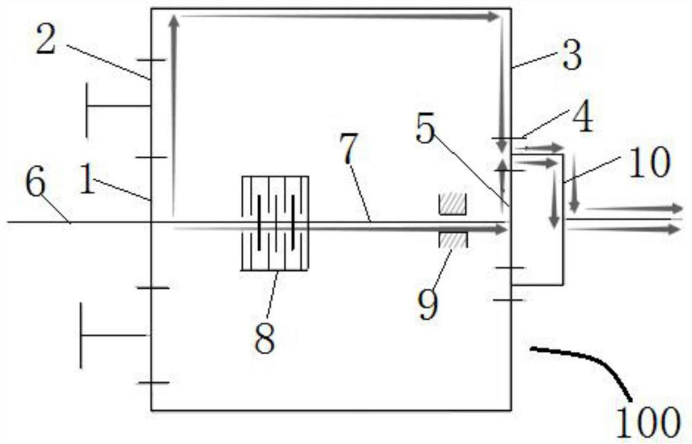
[0040] The purpose of the present invention is to provide a variable speed transmission system to solve the above-mentioned problems in the prior art, which can realize the different rotation speeds required by the helicopter in two different modes of hovering and cruising, and realizes a smooth speed change without a gap period .

[0041] In order to make the above objects, features and advantages of the present invention more comprehensible, the present inve...


PUM


Abstract

The invention discloses a variable speed transmission system, and relates to the technical field of transmission systems. The variable speed transmission system comprises a first planetary gear train in transmission connection with an input shaft; the first planetary gear train is connected with a second planetary gear train through a transmission shaft, and the second planetary gear train is connected with an output shaft; the first planetary gear train comprises a first sun gear in transmission connection with the transmission shaft and the input shaft, a first planetary gear externally meshes with the first sun gear, the end, away from the first sun gear, of the transmission shaft is in transmission connection with a second sun gear of the second planetary gear train, a second planetary gear externally meshes with the second sun gear, and the first planetary gear and the second planetary gear are in transmission connection through a gear ring; and a brake and a friction clutch are arranged on the transmission shaft. Different rotating speeds required in two different modes of hovering and cruising of a helicopter can be realized, and stable speed change and no neutral gear period are realized.

Description

technical field [0001] The invention relates to the technical field of transmission systems, in particular to a variable speed transmission system. Background technique [0002] Helicopters are widely used in various fields due to their vertical take-off and landing, hovering in the air, flexible flight in any direction, and no need for fixed airports and runways. my country's general-purpose helicopters and special-purpose armed helicopters are in a period of continuous development, with broad application prospects and rising demand. Demand traction has always been one of the main driving forces for scientific and technological progress, so the latest demand for helicopters will also promote the further development of basic science in related disciplines and key technologies in related industries. [0003] Transmission system, engine and rotor system are the three key moving parts of a helicopter. The function of the transmission system is to transmit the power and speed ...

Claims


Application Information

Patent Timeline
IPC IPC(8): F16H3/44F16H57/08B64D35/04
CPCF16H3/44F16H57/08F16H57/082B64D35/04F16H2057/087F16H2200/20F16H2200/203
Inventor 鲍和云杨星光李晗罗志洋周涛
Owner NANJING UNIV OF AERONAUTICS & ASTRONAUTICS
Learn More