Detection equipment and optical detection method

A testing equipment and optical testing technology, applied in optical testing for flaws/defects, material analysis by optical means, measuring devices, etc. High detection efficiency and accuracy, improved functional integration, and accurate positioning and navigation

Active Publication Date: 2021-06-22
TZTEK TECH
View PDF7 Cites 1 Cited by
  • Summary
  • Abstract
  • Description
  • Claims
  • Application Information

AI Technical Summary

Problems solved by technology

[0003] However, with the increasingly higher precision requirements and multi-functional integration requirements of testing equipment, as in the prior art, facing the detection of large-area DUTs, FPD boards, etc., the current solution is to use multiple CCD cameras in line method, which obviously caused a substantial increase in cost; another solution is to use a single camera plus drag chain to realize reciprocating motion for image scanning detection, which requires too high a speed of reciprocating motion; The high-precision requirements cannot be met, and for the reciprocating motion mode of the drag chain, the DUT cannot ensure high-precision positioning, which also reduces the detection accuracy
[0004] In addition, the traditional transmission mechanism is easy to scratch the test piece, and the pneumatic method is easy to cause vibration of the machine table and the outer cover, resulting in a decrease in accuracy
The large format adopts multi-row and multi-column matrix arrangement of nozzles, which is easy to leave marks on the substrate of the test piece
[0005] Furthermore, the traditional positioning and navigation only uses a mechanical positioning mechanism, and the accuracy cannot meet the requirements

Method used


Image

  • Detection equipment and optical detection method
  • Detection equipment and optical detection method
  • Detection equipment and optical detection method

Examples


Embodiment 1

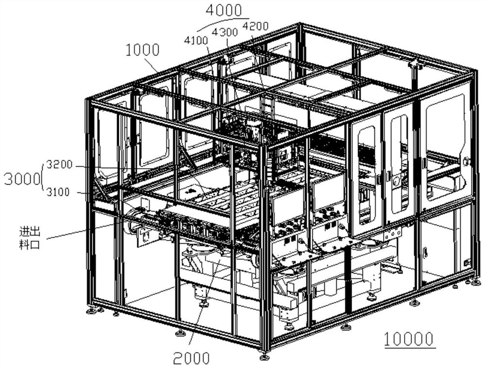
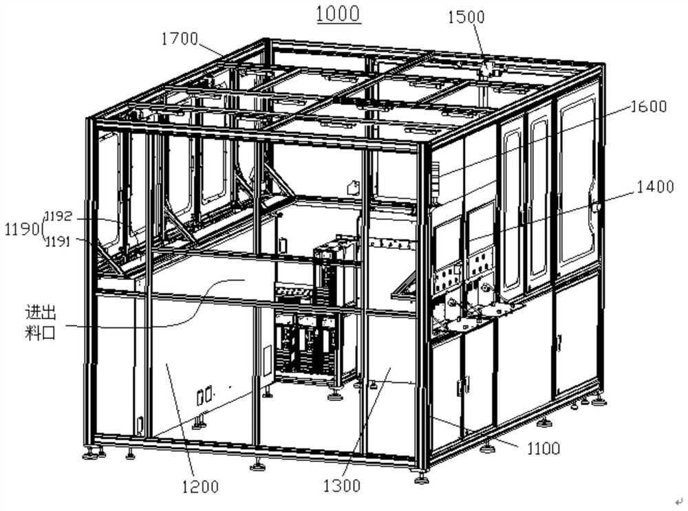
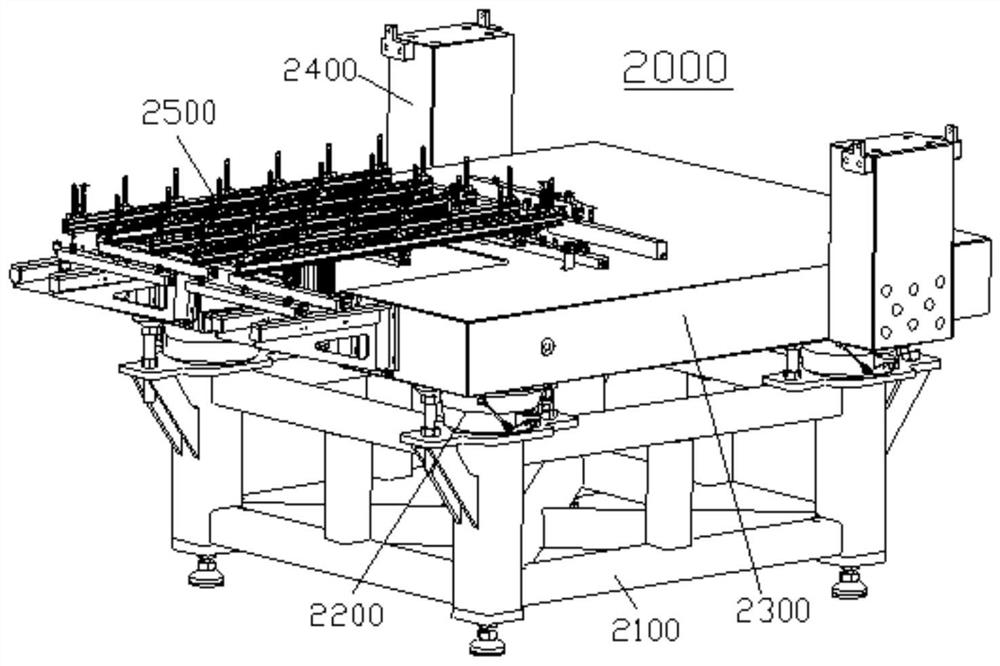
[0058] A detection device, see figure 1 , the detection equipment includes a functional outer box 1000 , a shock-absorbing stand 2000 , a platform module 3000 and an optical detection device 4000 .

[0059] Layout setting: the vibration-absorbing stand 2000 , the platform module 3000 and the optical detection device 4000 are non-rigidly connected or arranged at intervals in the functional outer box 1000 . Wherein, in the embodiment of interval setting, the minimum space between intervals is 3cm-20cm.

[0060] The platform module 3000 and the optical detection device 4000 are arranged on the vibration-absorbing stand 2000 .

[0061] The platform module 3000 is arranged on the shock absorbing platform 2000, and the platform module includes a transfer device 3100 and an air flotation platform 3200; the transfer device 3100 straddles the air flotation platform 3200 for treatment The test piece is transferred between the feeding port and the testing station. The air flotation pla...

Embodiment 2

[0112] An optical inspection method for a substrate-type object to be tested, the method includes the following steps.

[0113] S1 The initial positioning of material discharge, the substrate of the piece to be tested in the material box is transported to the transfer device 3100 of the platform module 3000 by manual or robotic hands, and the pre-check component 3140 of the transfer device 3100 performs a pre-detection whether there is a piece to be tested The substrate is sucked by the suction cup assembly 3160 from the lower surface, and the side rest assembly 3130 and the end rest assembly 3150 perform initial positioning.

[0114] S2 Feeding of the test piece, the two sets of side resting components 3130 retreat and the front end resting component 3150 retreats and descends below the substrate, and the transfer device 3100 transports the substrate of the test part to the air flotation platform along the feeding direction Detect initial bits on the 3200.

[0115] S3 detect...


PUM


Abstract

The invention discloses detection equipment and an optical detection method. The detection equipment comprises a functional outer box, a damping rack, a platform module and an optical detection device. The platform module comprises a transferring device and an air floating platform. The transferring device is arranged on the air floating platform in a crossing mode so as to transfer a to-be-detected piece between the feeding port and the detection station. The optical detection device comprises a main detection camera assembly, a redetection camera assembly and a positioning camera assembly. The optical detection method comprises the steps of feeding and initial positioning, to-be-detected piece feeding, detection positioning, map matching and initial detection, re-detection to obtain a detection result, detection completion and material returning. According to the equipment, the detection method is executed through the main detection camera assembly, the redetection camera assembly and the positioning camera assembly, positioning, initial detection and redetection of to-be-detected pieces of different specifications are achieved, positioning and navigation are accurate, the vibration absorption performance of the rack is good, the equipment cost is low, the detection efficiency and precision are high, the function integration degree of the whole machine is improved, and the whole machine is low in fault rate and convenient to maintain.

Description

technical field [0001] The invention relates to detection equipment and its parts technology, in particular to a detection equipment and an optical detection method. Background technique [0002] For the manufacturing process of motherboards and displays (such as FPC, flexible printed circuit, flexible printed circuit board, FPD, flat panel display-flat panel display) of 3C products such as computer-computer, communication-communication, and consumer electronics-consumerelectronics, it is necessary to The components in each process are inspected, and optical inspection equipment is most used in this type of inspection. Its basic structure includes feeding, testing, blanking, etc., so as to complete the defect detection and / or size measurement of the workpiece to be tested. [0003] However, with the increasingly higher precision requirements and multi-functional integration requirements of testing equipment, as in the prior art, facing the detection of large-area DUTs, FPD ...

Claims


Application Information

Patent Timeline
Patent Type & Authority Applications(China)
IPC IPC(8): G01N21/01G01N21/88
CPCG01N21/01G01N21/88G01N2021/0112
Inventor 张体瑞杨云仙谷孝东刘丽丽刘华雷曹葵康温延培
Owner TZTEK TECH
Why Eureka
Try Eureka