Simple and reliable power-on state detection circuit

A technology for detecting circuits and electrical states, applied in the field of detection, to achieve the effects of strong compatibility, convenient debugging, and continuous logic states

Active Publication Date: 2021-06-22
XIAN MICROELECTRONICS TECH INST
View PDF10 Cites 2 Cited by
  • Summary
  • Abstract
  • Description
  • Claims
  • Application Information

AI Technical Summary

Problems solved by technology

[0003] For electronic products with long life and long-term operation in the prior art, the judgment result of the actual voltage signal after power-on is usually used to indicate whether the product is normal or faulty, and there is no way to provide information on product quality changes during product use. To solve the problem of trend interpretation, the present invention provides a simple and reliable power-on state detection circuit. The circuit has a simple structure and is convenient to adjust. process safety

Method used


Image

  • Simple and reliable power-on state detection circuit
  • Simple and reliable power-on state detection circuit
  • Simple and reliable power-on state detection circuit

Examples


Embodiment

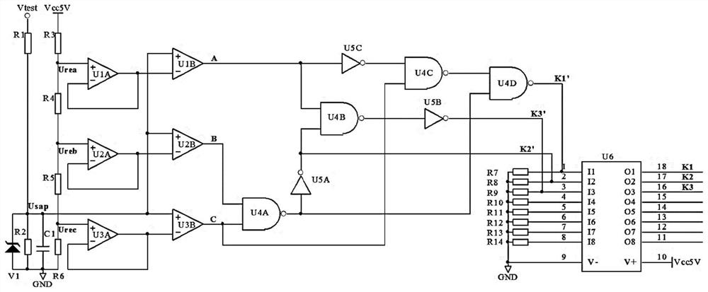
[0033]Firstly, the actual electrical characteristic voltage parameter collection of the product is realized by the resistor R1 and the resistor R2 voltage divider network. Collect power-on voltage signal V test The voltage generates the acquisition signal U sap ;

[0034] At the same time, according to the analysis of the design characteristics of the product, the change trend point of the power-on characteristic voltage parameter is determined. The first reference voltage U is generated respectively through the resistor R3, resistor R4, resistor R5 and resistor R6 voltage divider network rea , the second reference voltage U reb and the third reference voltage U rec , the first-stage operational amplifier unit includes operational amplifier U1A, operational amplifier U2A and operational amplifier U3A respectively designed as a unity-gain buffer state, and operational amplifier U1A converts the first reference voltage U rea , Operational amplifier U2A converts the second r...


PUM


Abstract

The invention provides a simple and reliable power-on state detection circuit. A signal acquisition circuit acquires a power-on voltage signal and generates an acquisition signal, the acquisition signal is compared with a reference voltage formed in a reference circuit, and then signal conversion is performed through a logic state conversion circuit; the acquisition signal is converted into an OC interface signal through the driver, so that a state indication circuit can be conveniently connected; the power-on state detection circuit detects state discrimination in a segmented manner through multi-point characteristic voltage, and is simple in structure and convenient to debug; meanwhile, the power-on state detection circuit is continuous in partition voltage output logic state, high in output interface compatibility and easy to adjust.

Description

technical field [0001] The invention relates to the technical field of detection, in particular to a simple and reliable power-on state detection circuit. Background technique [0002] At present, the power-on status of electronic products is usually used to indicate whether the product is normal or faulty by judging the presence or absence of the actual voltage signal after power-on. From the perspective of product users, it will be more humane to be able to prompt the trend of changes in the working quality of electronic products with long life and long-term operation. However, the current power-on status detection method does not have the ability to determine the working quality of products in use. Interpretation of changing trends. Contents of the invention [0003] For electronic products with long life and long-term operation in the prior art, the judgment result of the actual voltage signal after power-on is usually used to indicate whether the product is normal or...

Claims


Application Information

Patent Timeline
Patent Type & Authority Applications(China)
IPC IPC(8): G01R31/00G01R31/66G01R19/00
CPCG01R31/00G01R31/66G01R19/0084
Inventor 李刚
Owner XIAN MICROELECTRONICS TECH INST
Why Eureka
Try Eureka