Directional coupler and beam splitter thereof

A technology of directional coupler and coupled waveguide, which is applied to instruments, light guides, optics, etc., and can solve problems such as unfavorable processing, reduced bandwidth of directional couplers, and large insertion loss.

Pending Publication Date: 2021-06-22
ZHONGXING PHOTONICS TECH CO LTD
View PDF0 Cites 2 Cited by
  • Summary
  • Abstract
  • Description
  • Claims
  • Application Information

AI Technical Summary

Problems solved by technology

However, the combination of wide and narrow waveguides will reduce the bandwidth of the directional coupler relatively, and the insertion loss is large and the process sensitivity is high, which is not conducive to processing; while the arc-shaped curved waveguide has a large radius of curvature, it will not only lead Both the size and insertion loss increase, and the increased size will lead to an increase in the optical path, which will increase the phase error and degrade the performance of the device

Method used


Image

  • Directional coupler and beam splitter thereof
  • Directional coupler and beam splitter thereof
  • Directional coupler and beam splitter thereof

Examples


example 1

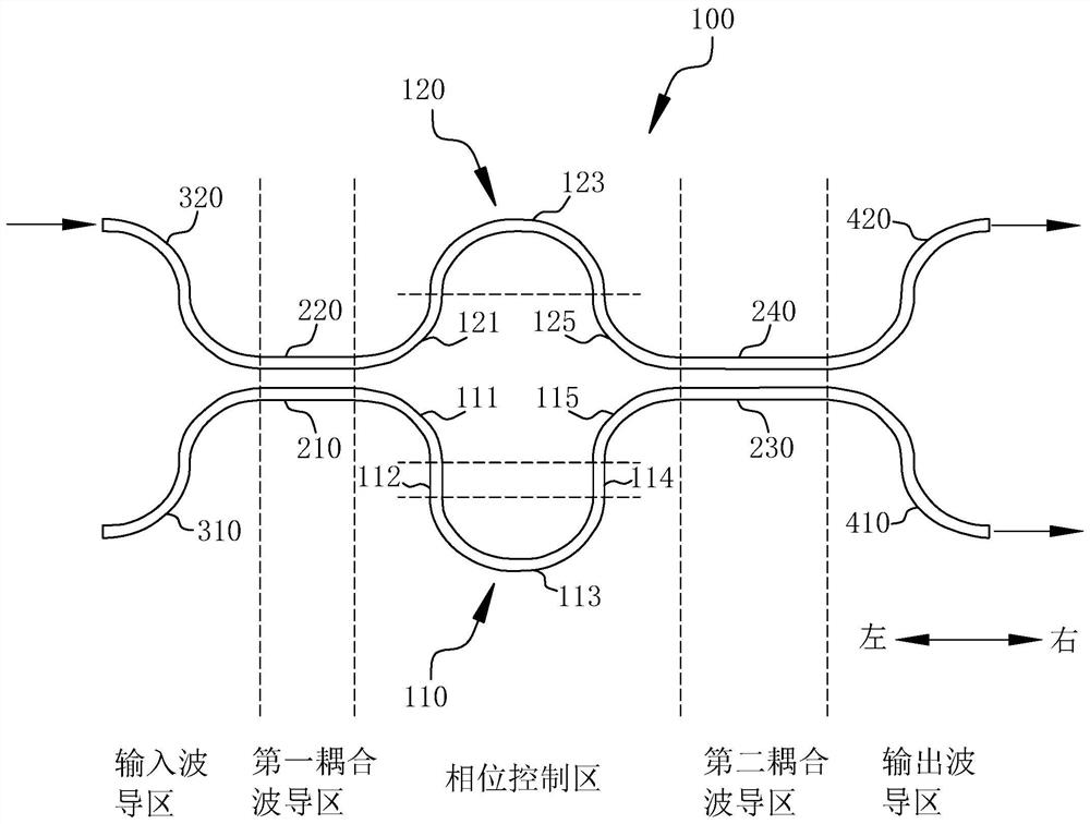
[0055] based on figure 1 In the shown structure, the input optical signal is input into the directional coupler 100 from the second input waveguide 320. When the input optical signal is transmitted to the first coupling waveguide region, the input optical signal will be divided into The through optical signal and the coupled optical signal transmitted in the first coupling waveguide 210, and subsequently, the through optical signal and the coupled optical signal respectively go through different optical paths in the corresponding first phase shifting arm 110 and the second phase shifting arm 120, Therefore, a specific phase difference is generated, and then, the through optical signal and the coupled optical signal with a phase difference between them will be coupled twice in the second coupling waveguide region, and then the first output waveguide 410 and the second output waveguide 420 are respectively Outputs two optical signals with a specific split ratio and has wide band...

example 2

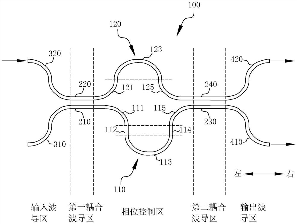
[0058] based on figure 1 In the shown structure, the input optical signal is input into the directional coupler 100 from the second input waveguide 320. When the input optical signal is transmitted to the first coupling waveguide region, the input optical signal will be divided into The through optical signal and the coupled optical signal transmitted in the first coupling waveguide 210, and subsequently, the through optical signal and the coupled optical signal respectively go through different optical paths in the corresponding first phase shifting arm 110 and the second phase shifting arm 120, Therefore, a specific phase difference is generated, and then, the through optical signal and the coupled optical signal with a phase difference between them will be coupled twice in the second coupling waveguide region, and then the first output waveguide 410 and the second output waveguide 420 are respectively Outputs two optical signals with a specific split ratio and has wide band...


PUM


Abstract

The invention discloses a directional coupler and a beam splitter thereof. The directional coupler comprises a first phase shifting arm formed by sequentially connecting a first bent waveguide, a first straight waveguide, a second bent waveguide, a second straight waveguide and a third bent waveguide, and a second phase shifting arm formed by sequentially connecting a fourth bent waveguide, a fifth bent waveguide and a sixth bent waveguide, wherein the first bent waveguide and the sixth bent waveguide are in central symmetry, the second bent waveguide and the fifth bent waveguide are in central symmetry, the third bent waveguide and the fourth bent waveguide are in central symmetry, and the first straight waveguide and the second straight waveguide are parallel and equal in length. The first straight waveguide and the second straight waveguide are both perpendicular to the direction from a first coupling waveguide area to a second coupling waveguide area. In the embodiment of the invention, the length of the device can be reduced under the condition of keeping a relatively large bandwidth, and the phase precision is ensured.

Description

technical field [0001] The embodiments of the present application relate to but are not limited to the technical field of silicon-based photonic integrated chips, and in particular relate to a directional coupler and a beam splitter thereof. Background technique [0002] In recent years, with the continuous improvement of the performance of various silicon photonic devices, fast, low-cost, highly integrated silicon-based photonic integrated chips have also been rapidly developed and gradually commercialized. As one of the basic components of silicon-based photonic integrated chips, coupling beam splitters can meet the requirements of silicon photonic chips for different coupling splitting ratios, and have always been a research hotspot in the industry. Optical couplers with low loss, small size, and large bandwidth are more It is the goal that the industry is constantly pursuing. The directional coupler with good bandwidth characteristics commonly used in silicon photonic c...

Claims


Application Information

Patent Timeline
Patent Type & Authority Applications(China)
IPC IPC(8): G02B6/10G02B6/12G02B6/125
CPCG02B6/10G02B6/12G02B6/125G02B2006/12147
Inventor 顾凯李凡沈百林
Owner ZHONGXING PHOTONICS TECH CO LTD
Why Eureka
Try Eureka