Photomask and photomask defect inspection method

A defect inspection and photomask technology, applied in the field of photomask and photomask defect inspection, can solve the problems of long creation cycle of defect scanning program, reducing machine utilization rate, occupying scanning time, etc., so as to save program creation time and program Shared probability, improved utilization, increased common effect

Pending Publication Date: 2021-06-22
GUANGZHOU CANSEMI TECH INC
View PDF5 Cites 0 Cited by
  • Summary
  • Abstract
  • Description
  • Claims
  • Application Information

AI Technical Summary

Problems solved by technology

Usually, it takes 1 to 2 hours to establish a defect scanning program for a single photomask, and since the photomask is a high-precision and fragile product, the loading requirements are strict and the loading is slow, and it takes 10 to 15 minutes to transfer to the photomask defect inspection station. Start the defect scanning program, and a set of masks can range from a few layers to as many as dozens of layers. The defect scanning program takes a long time to build and takes up the scanning time of other masks, reducing the utilization rate of the machine.

Method used


Image

  • Photomask and photomask defect inspection method
  • Photomask and photomask defect inspection method
  • Photomask and photomask defect inspection method

Examples


Embodiment Construction

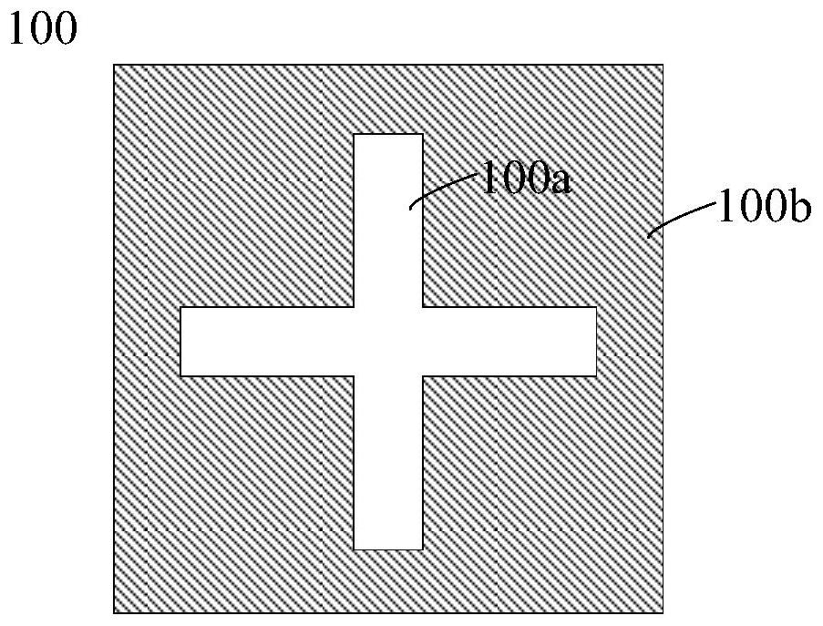
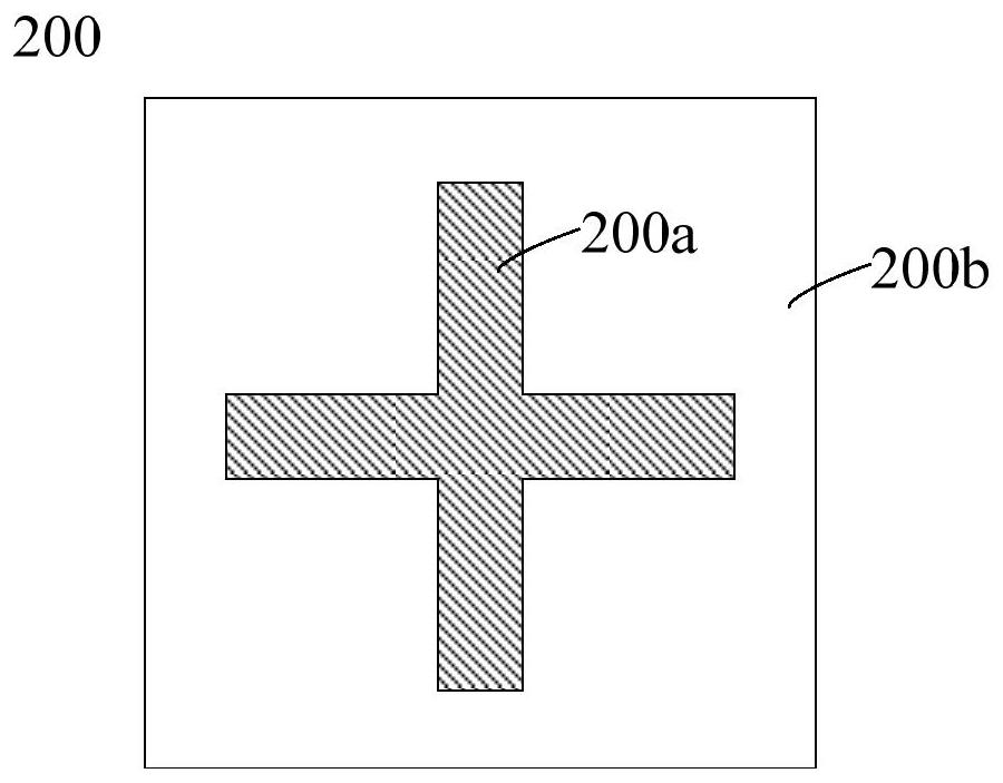
[0028] The photomask and the photomask defect inspection method of the present invention will be further described in detail below with reference to the accompanying drawings and specific embodiments. According to the following description and accompanying drawings, the advantages and characteristics of the present invention will be clearer, however, it should be noted that the concept of the technical solution of the present invention can be implemented in many different forms, and is not limited to the specific implementation set forth herein. example. The drawings are all in very simplified form and use imprecise scales, and are only used to facilitate and clearly assist the purpose of illustrating the embodiments of the present invention.

[0029] The terms "first", "second", etc. in the specification are used to distinguish between similar elements, and are not necessarily used to describe a specific order or chronological order. It is to be understood that the terms so ...


PUM


Abstract

According to a photomask and a photomask defect inspection method provided by the invention, a mark pattern is arranged in a cutting channel region of the photomask, and a defect inspection program of the photomask is established by taking the coordinate of the mark pattern as the reference point, so that the photomask defect inspection program is established under the condition of complete offset, and the defect inspection program is established without occupying the scanning time of other photomasks; the utilization rate of the sheet sweeping machine is improved; and the defect inspection program of the photomask is established by taking the coordinates of the mark pattern as reference points, so that the establishment period of the defect program can be greatly shortened, and manpower is saved. Furthermore, image calibration can be carried out by taking the mark pattern as a light source calibration point and a cutting channel characteristic pattern calibration point, so that the defect inspection program of the multilayer photomask has the same light source calibration point and the same cutting channel characteristic pattern calibration point, the generality of the defect inspection program is improved, the program establishment time and the program sharing probability are further saved, and the inspection efficiency of the machine is improved to a certain extent.

Description

technical field [0001] The invention relates to the technical field of semiconductors, in particular to a photomask and a method for inspecting the defect of the photomask. Background technique [0002] A photolithography mask, also known as a photomask, is a master pattern used in the photolithography process of an integrated circuit. The production process of a product chip usually needs to go through dozens of photolithography times, and each photolithography requires a photomask. Photolithography, which replicates patterns onto wafers in a manner similar to photoprocessing. The quality of the photomask affects the quality of the product. When the photomask is irradiated by the laser of the lithography machine for a certain period of time, it will produce haze defects. Once the haze defect occurs, it will have a great impact on the yield of the product. The photomask Usually it can only be sent back to the mask factory for repair. Therefore, it is particularly important...

Claims


Application Information

Patent Timeline
Patent Type & Authority Applications(China)
IPC IPC(8): G03F1/44G03F1/84G01N21/958
CPCG03F1/44G03F1/84G01N21/958
Inventor 龙春艳周宏玉
Owner GUANGZHOU CANSEMI TECH INC
Why Eureka
Try Eureka