
Automatic drying and heated air circulation energy-saving device for graphene underfloor heating

A hot air circulation and energy-saving device technology, which is applied to the surface coating liquid device, pretreatment surface, coating, etc., can solve the problem of single function of the heating device, cannot cool down, can only be heated, etc.

Pending Publication Date: 2021-06-25
河北博峰新能源科技有限公司
View PDF0 Cites 0 Cited by
  • Summary
  • Abstract
  • Description
  • Claims
  • Application Information

AI Technical Summary

Problems solved by technology

[0004] The purpose of the present invention is to solve the problem that the heating device has a single function, can only heat, and cannot cool down after exceeding the temperature setting value, and proposes a graphene floor heating automatic drying, hot air circulation energy-saving device

Method used


Image

  • Automatic drying and heated air circulation energy-saving device for graphene underfloor heating
  • Automatic drying and heated air circulation energy-saving device for graphene underfloor heating
  • Automatic drying and heated air circulation energy-saving device for graphene underfloor heating

Examples


Embodiment 1

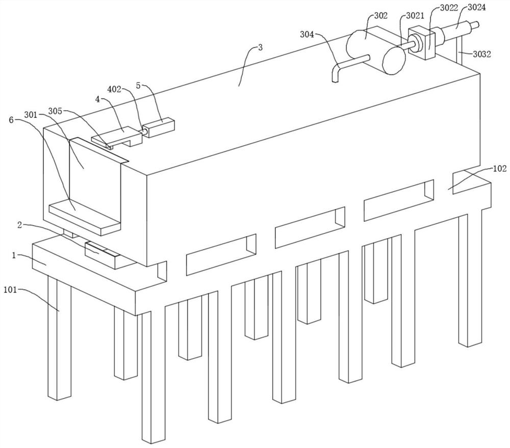
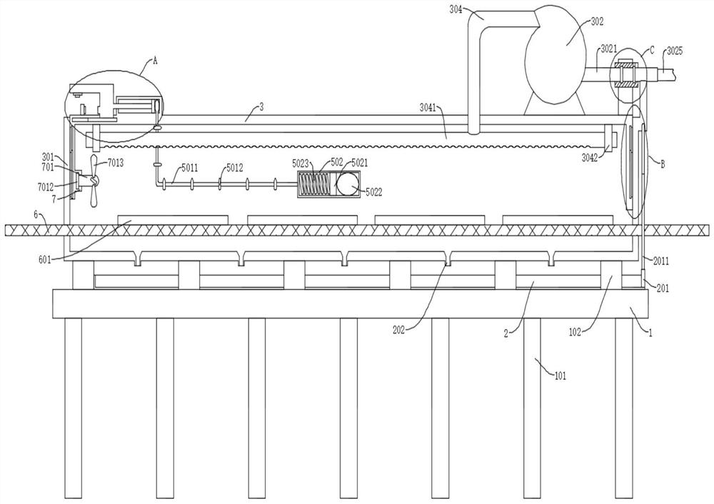
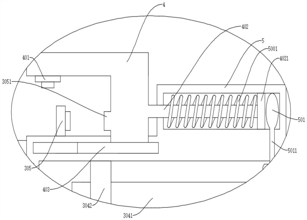
[0027] refer to Figure 1-5 , a graphene floor heating automatic drying, hot air circulation energy-saving device, including a workbench 1, a drying box 3 is fixedly connected to the workbench 1, a steel belt 6 is slidably connected to the inside of the drying box 3, and a steel belt 6 is placed on the steel belt 6 Electric heater 601, fan 302 is fixedly connected on drying box 3, air inlet pipe 304 and exhaust pipe 3021 are fixedly connected on fan 302, ventilation pipe 3041 is fixedly connected in drying box 3, and ventilation pipe 3041 is provided with Vent, the air inlet pipe 304 is fixedly connected to the ventilation pipe 3041, the drying box 3 is fixedly connected to the connection block 3023, the exhaust pipe 3021 is fixedly connected to the connection block 3023, and the connection block 3023 is slidably connected to the connection pipe 3024. The connecting pipe 3024 is fixedly connected with the hot air pipe 3025, the right end of the drying box 3 is slidably connect...

Embodiment 2

[0030] refer to Figure 1-5 , is basically the same as in Embodiment 1, and furthermore, a fixed block 7 is fixedly connected in the drying box 3, a rotating shaft 701 is rotatably connected to the fixed block 7, a blade 7013 is fixedly connected to the rotating shaft 701, and a blade 7013 is fixedly connected to the rotating shaft 701. The swivel 7012 is rotatably connected in the fixed block 7, the first fixed frame 4 is fixedly connected with the second switch 401 for controlling the rotation of the rotating shaft 701, and the second door 301 is offset against the second switch 401.

Embodiment 3

[0032] refer to Figure 1-5 , is basically the same as that of Embodiment 1, furthermore, the workbench 1 is fixedly connected with the water collecting tank 2, the drying box 3 is fixedly connected with the drain pipe 202 matched with the water collecting tank 2, and the water collecting tank 2 is slidably connected with a plug The plate 201 and the blocking plate 201 are fixedly connected with a second fixing frame 2011 , and the second fixing frame 2011 is fixedly connected with the first box door 303 .


PUM


Abstract

The invention discloses an automatic drying and heated air circulation energy-saving device for graphene underfloor heating, and belongs to the technical field of graphene electric heating radiator production devices. The automatic drying and heated air circulation energy-saving device for graphene underfloor heating comprises a worktable; the worktable is fixedly connected with a drying oven; the drying oven is fixedly connected with a blower; and the blower is fixedly connected with an air inlet pipe and an exhaust pipe. A first air bag is fixedly connected in a first piston cylinder; a first fixing rack is fixedly connected with a piston rod; the piston rod is fixedly connected with a first piston handle which is slidably connected in the first piston cylinder; the first air bag is abutted against the first piston handle; and the piston rod is sleeved with a reset spring. A second air bag is fixedly connected in the first piston handle; the second air bag is abutted against the second piston handle; and the first air bag is fixedly connected with the second piston cylinder through an air pipe. When the temperature in the drying oven exceeds the set temperature, cooling is automatically conducted; the sensitivity is high; and condensate water in the drying oven can be discharged during cooling.

Description

technical field [0001] The invention relates to the technical field of graphene electric heater production devices, in particular to a graphene floor heating automatic drying and hot air circulation energy-saving device. Background technique [0002] During the production process of the floor heating module, the graphene electric heater sprayed with graphene slurry needs to be dried. [0003] At present, most of the drying ovens for drying raw materials are only equipped with automatic heating devices, which can only be controlled by a single heating. When the temperature exceeds the set value, it cannot automatically cool down, resulting in product scrap or serious failure. Contents of the invention [0004] The purpose of the present invention is to solve the problem that the heating device has a single function, can only heat, and cannot cool down after the temperature exceeds the set value, and proposes a graphene floor heating automatic drying and hot air circulation ...

Claims


Application Information

Patent Timeline
IPC IPC(8): B05D3/04
CPCB05D3/0413
Inventor 黄项州夏雨静黄诗淇夏宇皓
Owner 河北博峰新能源科技有限公司
Learn More