Integrated power supply equipment

A technology for power supply equipment and cabinets, applied in the field of integrated power supply equipment, can solve the problems of reduced heat dissipation of the power supply cabinet and inability to fully exert the operation performance of the power supply cabinet, and achieve the effect of reducing weight

Pending Publication Date: 2021-06-25
邱柔媚
View PDF0 Cites 1 Cited by
  • Summary
  • Abstract
  • Description
  • Claims
  • Application Information

AI Technical Summary

Problems solved by technology

[0004] Because cotton dust has strong adsorption when it is damp, if the power cabinet works in a textile workshop with low room temperature, the high temperature generated inside the power cabinet will form moisture when it meets the cold air in the workshop

Method used


Image

  • Integrated power supply equipment
  • Integrated power supply equipment
  • Integrated power supply equipment

Examples


Embodiment 1

[0029] as attached figure 1 to attach Figure 6 Shown:

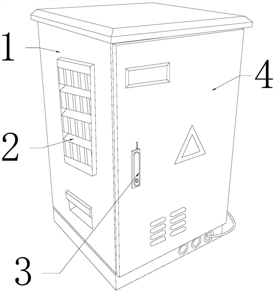
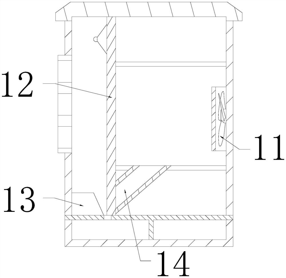
[0030] The invention provides an integrated power supply device, the structure of which includes a box body 1, a ventilation plate 2, a handle 3, and a box door 4. The ventilation plate 2 is installed on the left side of the box body 1, and the handle 3 is embedded in the box The front end of the door 4, the right side of the box door 4 is hingedly connected with the box body 1, and the box body 1 is provided with a cooling fan 11, a heat conducting plate 12, a limiting plate 13, and an air duct 14, and the cooling fan 11 Installed inside the box body 1, the upper and lower ends of the heat conduction plate 12 are respectively embedded and connected with the inside of the box body 1, the limit plate 13 is installed in the lower left corner of the box body 1, and the air guide tube 14 is embedded with the heat conduction plate 12. The air guide pipe 14 can guide the wind blown by the heat dissipation fan 11 into the hea...

Embodiment 2

[0038] as attached Figure 7 to attach Figure 8 Shown:

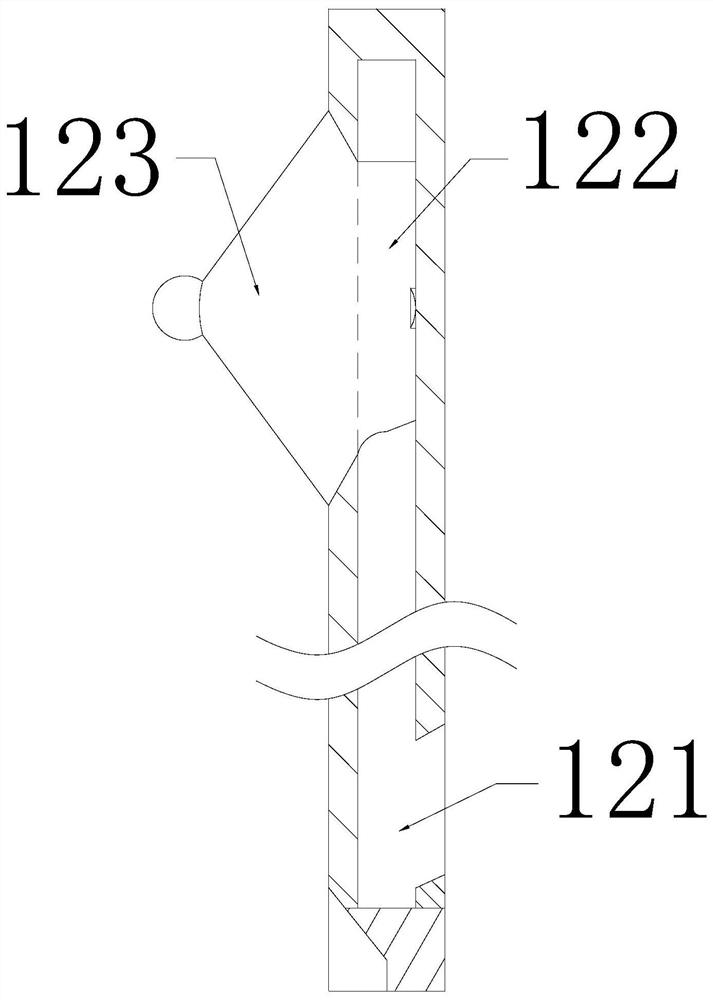
[0039] The present invention provides an integrated power supply device. The limit plate 13 is provided with a push-pull bar 131, a receiving block 132, and a chip removal block 133. The push-pull bar 131 is embedded in the upper right corner of the limit plate 13. The receiving block The left end of 132 slides between the limiting plate 13 and the chip removal block 133, and the right end is embedded and connected with the push-pull bar 131. The chip removal block 133 cooperates with the internal clearance of the limit plate 13, and the push-pull bar 131 is along the limit plate. 13 is installed at a slope angle on the right side, and has good resilience. The chip removal block 133 is installed at 45 degrees to the horizontal direction of the limit block 13, which is conducive to scraping the top of the scraper block 123. When the scraper block 123 falls to At the bottom of the heat conducting plate 12, the push-pull...


PUM


Abstract

The invention provides integrated power supply equipment which structurally comprises a box body, a ventilation plate, a handle and a box door. The ventilation plate is installed at the left side of the box body, the handle is fixedly embedded at the front end of the box door, and the right side of the box door is hinged to the box body. According to the integrated power supply equipment, air flow blown out by a heat dissipation fan is guided into a heat conduction plate through an air guide pipe, so that the air flow pushes a scraping plate upwards, wet cotton dust adsorbed on the heat conduction plate is removed, the problem that the heat dissipation performance of a power supply cabinet is reduced due to the fact that the heat conduction plate is covered by the wet cotton dust layer by layer is avoided, and the operation performance of the power supply cabinet can be effectively played; and the scraping plate falls to the bottom end of the heat conduction plate, a push-pull strip is pressed to push a scrap removing block out through a bearing block, the wet cotton dust left on the top of the scraping plate is removed, scraped objects on the top of the scraping plate can be removed, the weight of the scraping plate is reduced, it is ensured that pushing by the air flow is easier, and the subsequent scraping action of the scraping plate is facilitated.

Description

technical field [0001] The invention belongs to the field of power supply systems, and more specifically relates to an integrated power supply device. Background technique [0002] The integrated power supply cabinet is a combined device composed of a DC power supply and other power supplies. The power supply device includes a DC power supply, an AC uninterruptible power supply for electric power, an inverter power supply for electric power, and a DC conversion power supply for communication, etc., and the DC power supply is shared. The battery pack is widely used in power grids, substations and other power generating institutions. [0003] Based on the above description, the inventors found that the existing integrated power supply mainly has the following deficiencies, such as: [0004] Because cotton dust has strong adsorption when it is damp, if the power cabinet works in a textile workshop with low room temperature, the high temperature generated inside the power cabin...

Claims


Application Information

Patent Timeline
IPC IPC(8): B08B1/00B08B13/00
CPCB08B1/001B08B1/007B08B13/00
Inventor 邱柔媚
Owner 邱柔媚
Why Eureka
Try Eureka