Metal clad plate rolling method for forming interlaced bonding interface

A metal clad plate, metal plate technology, applied in metal rolling, metal rolling, metal processing equipment and other directions, can solve the problems of easy warpage, low interface bonding strength of metal clad plate, low yield rate, etc., to prevent warping bending, good flexural strength, and low equipment requirements

Pending Publication Date: 2021-06-25
TAIYUAN UNIV OF TECH
View PDF17 Cites 2 Cited by
  • Summary
  • Abstract
  • Description
  • Claims
  • Application Information

AI Technical Summary

Problems solved by technology

[0003] The invention aims to solve the technical problems of low interfacial bonding strength, easy warping and low yield of metal clad plates made by existing rolling methods

Method used


Image

  • Metal clad plate rolling method for forming interlaced bonding interface
  • Metal clad plate rolling method for forming interlaced bonding interface
  • Metal clad plate rolling method for forming interlaced bonding interface

Examples


Embodiment 1

[0032] refer to Figure 1-9 , a method for rolling a Mg / Al clad plate forming an interwoven bonding interface, comprising the steps of:

[0033] S1. Preparation: Select the 5052 brand aluminum alloy plate with relatively small deformation resistance as the substrate 1, the length, width and height are 100mm, 100mm, and 2mm respectively, and select the AZ31 brand magnesium alloy plate with relatively large deformation resistance as the doubler plate 5, the length and width The heights are 100 mm, 100 mm, and 2 mm respectively, and the base plate 1 and the double plate 5 are respectively rolled by using a corrugated rolling mill in which the upper roll is a one-way corrugated roll 2 and the lower roll is a cross corrugated roll 9. The radial section of the cross corrugated roll 9 is The line equation is Wherein R is the radius of the cross corrugated roller 9, 0≤t≤1, and the axial section line equation is Where 0≤t≤1, the corrugation curve parameters of the one-way corrugate...

Embodiment 2

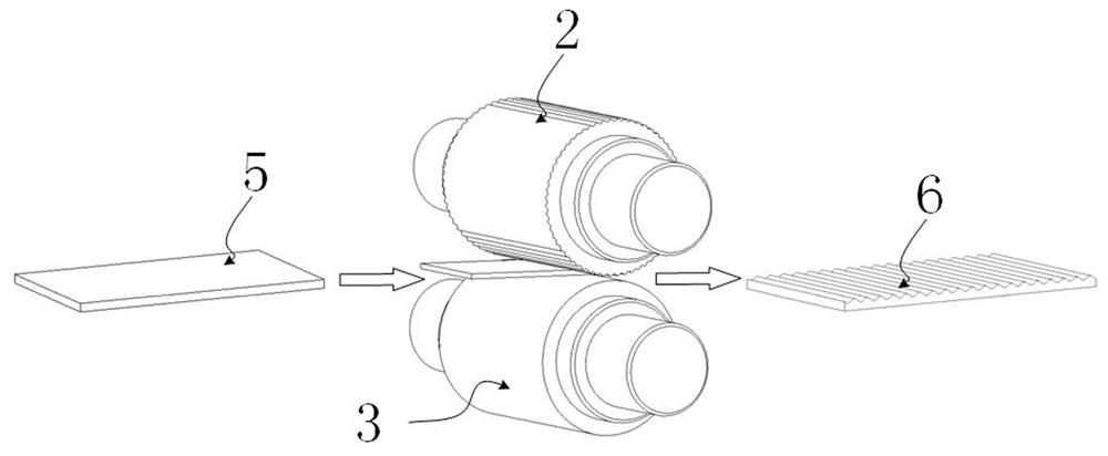
[0039] refer to Figure 1-4 , a method for rolling a Mg / Al clad plate forming an interwoven bonding interface, comprising the steps of:

[0040] S1. Preparation: Select the 5052 aluminum alloy plate with relatively small deformation resistance as the substrate 1, the length, width and height are 100mm, 100mm, and 2mm respectively, and select the AZ31 magnesium alloy plate with relatively large deformation resistance as the double plate 2, the length and width The heights are 100 mm, 100 mm, and 2 mm respectively, and the base plate 1 and the double plate 5 are respectively rolled using a corrugated rolling mill in which the upper roll is a one-way corrugated roll 2 and the lower roll is a flat roll 3. The radial cross-section of the one-way corrugated roll 2 is The equation of the radial section of the equation is Wherein R is the radius of the intersecting corrugated roll 9, 0≤t≤1, the linear velocity of the unidirectional corrugated roll 2 and the flat roll 3 are both 7.5m...


PUM


Abstract

The invention relates to the technical field of metal clad plate preparation, in particular to a metal clad plate rolling method for forming an interlaced bonding interface, and aims to solve the technical problems that a metal clad plate manufactured by adopting an existing rolling method is low in interface bonding strength, easy to warp, low in yield and the like. According to the technical scheme, corrugated surfaces are prefabricated on a base plate and a compound plate through a corrugated flat rolling machine, the corrugated surfaces of the base plate and the compound plate are oppositely stacked at 90 degrees when a clad plate blank is made, and then flat rolling is conducted. Compared with a traditional rolling method, the method is simple in blank making, cross rolling between the base plate and the compound plate can promote cracking of an oxide layer at a bonding interface and extrusion of fresh and activated metal atoms to the maximum extent, larger-range metallurgical bonding between the two kinds of metal is achieved, and the metal clad plate with high bonding interface strength and good upper and lower surface quality can be prepared.

Description

technical field [0001] The invention relates to the technical field of metal composite plate rolling, in particular to a metal composite plate rolling method for forming an interwoven bonding interface. Background technique [0002] The metal composite panel is a composite material that is made of two or more layers of heterogeneous metals processed by a special process to achieve interfacial metallurgical bonding. It can integrate high strength, high toughness, wear resistance, corrosion resistance and other excellent properties of component metal materials. At the same time, metal composite panels can also save precious metal materials and reduce product costs. At present, the manufacturing methods of metal composite panels include explosive composite method, diffusion composite method, hot / cold rolling composite method, etc. Among them, the explosive composite method and the diffusion composite method generally have the disadvantages of low interface bonding rate, uneven...

Claims


Application Information

Patent Timeline
Patent Type & Authority Applications(China)
IPC IPC(8): B21B1/38B21B47/00B21B45/00
CPCB21B1/38B21B47/00B21B45/004B21B2001/386
Inventor 冯光申依伦郜豪杰张恒马晓宝和东平
Owner TAIYUAN UNIV OF TECH
Why Eureka
Try Eureka