
Spoke air hole stamping equipment
A stamping and air hole technology, applied in metal processing equipment, perforation tools, presses, etc., can solve the problems of hidden safety hazards, low efficiency and high defective rate, and achieve the effect of improving the yield rate and preventing shaking.
- Summary
- Abstract
- Description
- Claims
- Application Information
AI Technical Summary
Problems solved by technology
Method used
Image

Examples
Embodiment Construction
[0031] The technical solutions of the present invention will be clearly and completely described below in conjunction with the embodiments. Apparently, the described embodiments are only some of the embodiments of the present invention, not all of them. Based on the embodiments of the present invention, all other embodiments obtained by persons of ordinary skill in the art without creative efforts fall within the protection scope of the present invention.
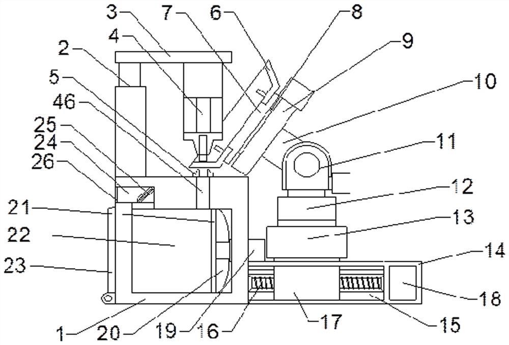
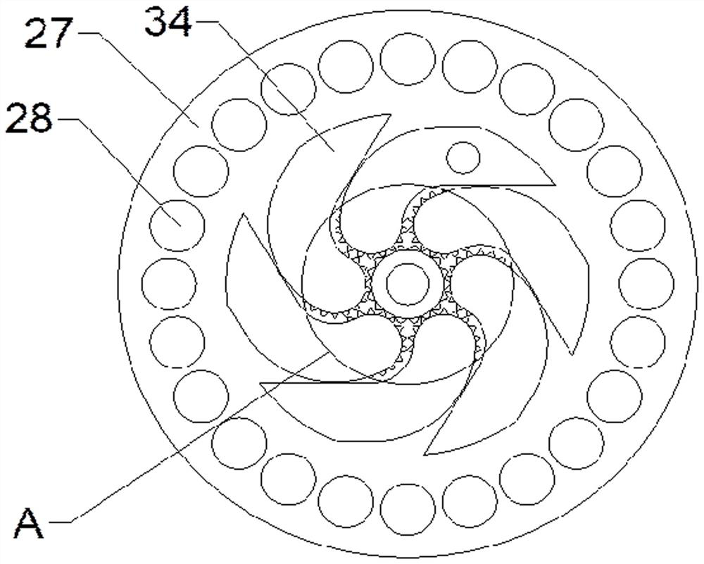
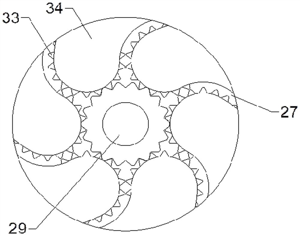
[0032] see Figure 1-7 Shown: a stamping processing equipment for spoke air holes, including a supporting box 1, a stamping body 4, a mounting seat mechanism 7, a first indexing mechanism 9 and a second indexing mechanism 11, and one side of the upper surface of the supporting box 1 The first elevating rod 2 is installed, and the upper end of the first elevating rod 2 is fixedly connected to one side of the lower surface of the supporting plate 3, and the other side of the lower surface of the supporting plate 3 is equipped...
PUM
 Abstract
Description
Claims
Application Information