Workbench with binding function for industrial design

An industrial design and workbench technology, applied in workbenches, manufacturing tools, workpiece clamping devices, etc., can solve the problems of fixed size and area of ​​the workbench, damage, and high cost, to meet the needs of placement, good placement and use, The effect of improving performance

Pending Publication Date: 2021-06-25
CHINA ACAD OF ART
View PDF5 Cites 0 Cited by
  • Summary
  • Abstract
  • Description
  • Claims
  • Application Information

AI Technical Summary

Problems solved by technology

[0005] Aiming at the deficiencies of the prior art, the present invention provides a workbench for industrial design with a binding function, which has the advantages of being able to quickly adjust the workbench and better meet people's needs for design and use, and solves the problems in the market. The form of the table is fixed when it is in use, and it is not easy to adjust and use. For some height-adjustable workbenches, most of them are adjusted by electric push rods, which not only has poor self-locking performance, but also requires multiple electric push rods for height adjustment, resulting in The cost is high, and the problem of damage is greater, and the size of the workbench is fixed. It is not easy to adjust and use when more items need to be placed, and the workbench often requires a lot of binding operations during use. The current workbench It does not have the binding function and is not convenient for design and use

Method used


Image

  • Workbench with binding function for industrial design
  • Workbench with binding function for industrial design
  • Workbench with binding function for industrial design

Examples


Embodiment Construction

[0028] The technical solutions in the embodiments of the present invention will be clearly and completely described below. Obviously, the described embodiments are only some of the embodiments of the present invention, but not all of them. Based on the embodiments of the present invention, all other embodiments obtained by persons of ordinary skill in the art without making creative efforts belong to the protection scope of the present invention.

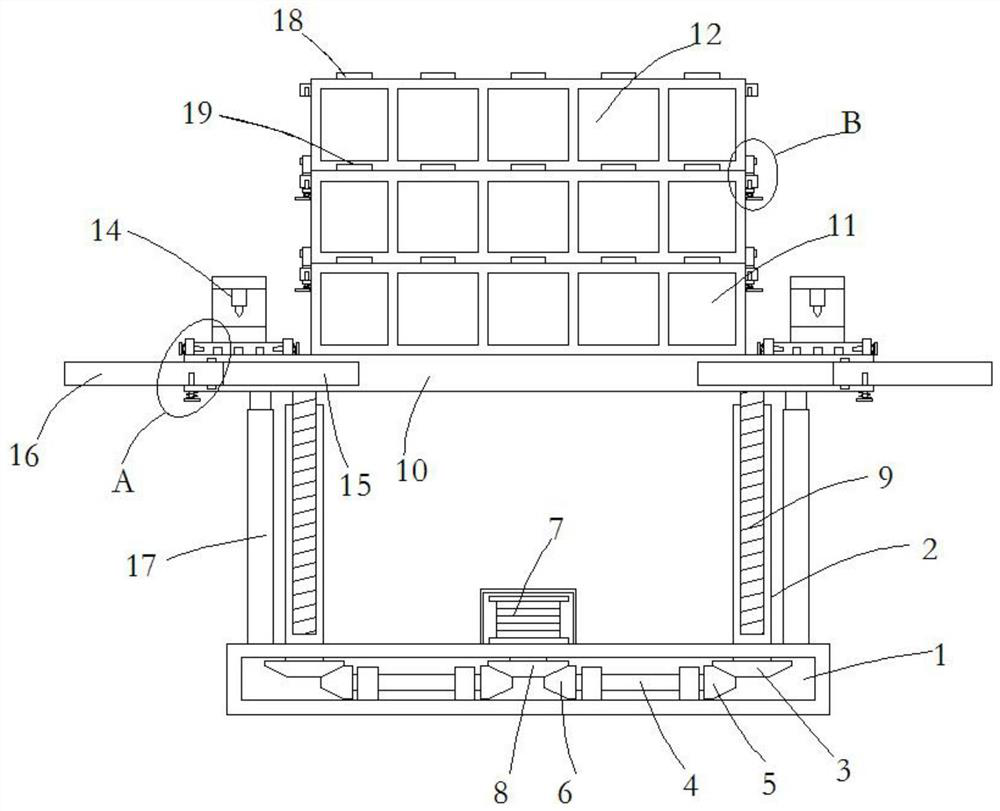
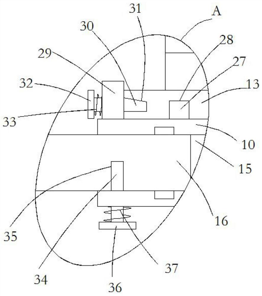
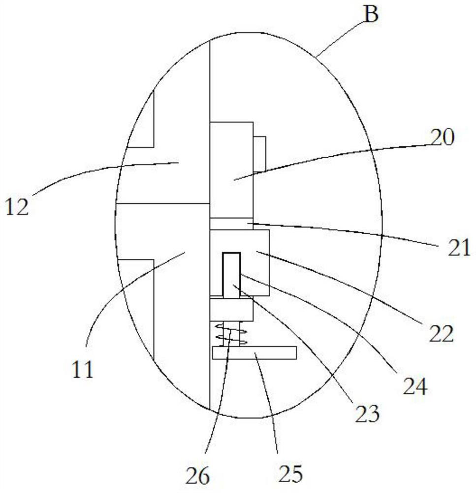
[0029] see Figure 1-4, a workbench for industrial design with a binding function, comprising a hollow base 1, through holes are opened at the four corners of the upper end of the hollow base 1, and a rotating screw barrel 2 is sleeved in the through holes through ball bearings, and the rotating screw barrel The lower end of 2 penetrates into the hollow base 1 and is fixedly connected with the first driven bevel gear 3. The inner wall of the bottom of the hollow base 1 is symmetrically rotated and connected with four connecting rods...


PUM


Abstract

The invention relates to the technical field of industrial design, and discloses a workbench with a binding function for industrial design. The workbench with the binding function for industrial design comprises a hollow base, wherein through holes are formed in four corners of the upper end of the hollow base; rotating screw cylinders are rotatably sleeved in the through holes through ball bearings; the lower ends of the rotating screw cylinders penetrate through and extend into the hollow base and are fixedly connected with first driven bevel gears; four connecting rods are symmetrically and rotationally connected to the inner wall of the bottom of the hollow base through multiple ball bearings; one end of each connecting rod is fixedly connected with a first driving bevel gear meshed with the first driven bevel gear correspondingly; the other end of the connecting rod is fixedly connected with a second driven bevel gear; and a driving motor is fixedly arranged at the center of the upper end of the hollow base. The workbench with the binding function for industrial design has the advantages that the workbench can be rapidly adjusted, and the design and use requirements of people can be better met.

Description

technical field [0001] The invention relates to the technical field of industrial design, in particular to an industrial design workbench with binding function. Background technique [0002] Industrial design is divided into four categories: product design, environmental design, communication design and design management; including modeling design, mechanical design, circuit design, clothing design, environmental planning, interior design, architectural design, UI design, graphic design, packaging design, advertising Design, animation design, display design and website design, etc. Industrial design is also called industrial product design. Industrial design involves psychology, sociology, aesthetics, ergonomics, mechanical structure, photography and color science, etc. Industrial development and The industrial design brought about by the division of labor is obviously different from other arts, production activities, crafts, etc. It is a cross product of various disciplines...

Claims


Application Information

Patent Timeline
IPC IPC(8): B25H1/16B25H1/12B25B11/00
CPCB25H1/16B25H1/12B25B11/00
Inventor 周东红
Owner CHINA ACAD OF ART
Why Eureka
Try Eureka