Drilling rock core box suitable for placing rock cores with different apertures
A core and aperture technology, applied in the direction of internal accessories, etc., can solve the problems of low practicability of the core box and difficult to adapt to the core, and achieve the effect of improving practicability, improving efficiency and saving costs.
- Summary
- Abstract
- Description
- Claims
- Application Information
AI Technical Summary
Problems solved by technology
Method used
Image
Examples
Embodiment 1
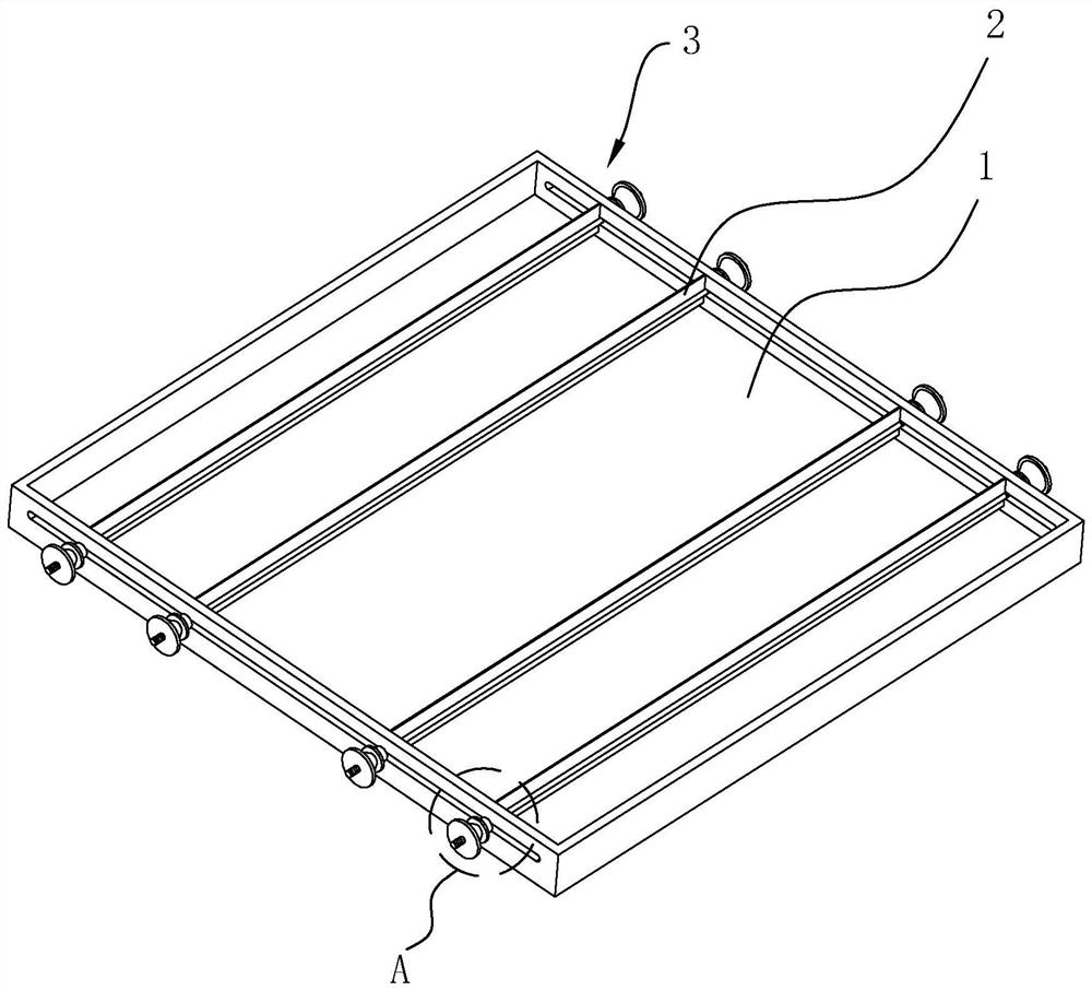
[0041] refer to figure 1 , the core box includes a box body 1 and some partitions 2, some partitions 2 are arranged in the box body 1, several partitions 2 are arranged in the box body 1 in turn, and the placement of the rock core is formed between adjacent partitions 2 Area; the embodiment in this application all selects the specification inside the core box to be 1000mm*60mm*1000mm, and the specification of partition 2 is 1000mm*50mm*2mm; partition 2 is selected as galvanized sheet, and partition 2 bottom wall and There is a gap between the inner bottom wall of the box body 1 .
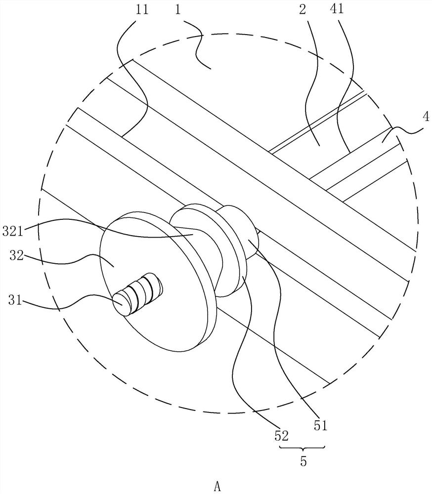
[0042] refer to figure 1 and figure 2 , the partition 2 is provided with a reinforcing rod 4, and the reinforcing rod 4 is provided with a jack 41, the jack 41 runs through the length direction of the reinforcing rod 4, and the partition 2 is inserted in the jack 41, and the length of the partition 2 The direction is consistent with the length direction of the reinforcing rod 4, and the reinforc...
Embodiment 2
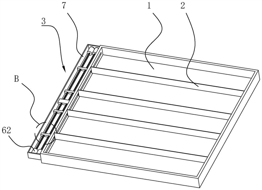
[0051] refer to image 3 , the core box includes a box body 1 and some partitions 2, some partitions 2 are arranged in the box body 1, several partitions 2 are arranged in the box body 1 in turn, and the placement of the rock core is formed between adjacent partitions 2 area.
[0052] refer to image 3 , the outer wall of the box body 1 is provided with an installation frame 7, the installation frame 7 is fixed on the box body 1 by gluing, an installation area is formed between the installation frame 7 and the box body 1, and an adjustment assembly 3 is arranged in the installation area, and the adjustment assembly 3 Located on one side of the partition 2, the adjustment assembly 3 is used to adjust the movement lock of the partition 2.
[0053] refer to image 3 and Figure 4 , the adjustment assembly 3 includes a screw mandrel 6, a slider 61 and a drive motor 62, the drive motor 62 is a servo motor, the drive motor 62 is fixed on the inner wall of the installation frame ...
Embodiment 3
[0058] refer to Figure 5 , the core box includes a box body 1 and some partitions 2, some partitions 2 are arranged in the box body 1, several partitions 2 are arranged in the box body 1 in turn, and the placement of the rock core is formed between adjacent partitions 2 area.
[0059] refer to Figure 5 and Image 6 , the outer wall of the box body 1 is provided with a protective frame 9, the protective frame 9 is fixed on the box body 1 by gluing, and a protective area is formed between the protective frame 9 and the box body 1; the two ends of the partition 2 in the length direction are provided with adjustment Component 3, part regulation Component 3 is located in the protected area.
[0060] refer to Image 6 , the adjustment assembly 3 includes an adjustment magnetic part 8 and an auxiliary magnetic part 81, the adjustment magnetic part 8 is a common magnet, and the auxiliary magnetic part 81 is a common magnet; The inner side wall is provided with a chute 12, the c...
PUM
 Abstract
Description
Claims
Application Information
 - R&D
- Intellectual Property
- Life Sciences
- Materials
- Tech Scout
- Unparalleled Data Quality
- Higher Quality Content
- 60% Fewer Hallucinations
Browse by: Latest US Patents, China's latest patents, Technical Efficacy Thesaurus, Application Domain, Technology Topic, Popular Technical Reports.
© 2025 PatSnap. All rights reserved.Legal|Privacy policy|Modern Slavery Act Transparency Statement|Sitemap|About US| Contact US: help@patsnap.com


