Furnace tube cleaning method

A furnace tube and cleaning technology, used in cleaning methods and utensils, cleaning hollow objects, chemical instruments and methods, etc., can solve problems such as dust pollution of silicon wafers and graphite boats, achieve good dust reduction effect, and prevent adhesion to materials. The effect of surface, reducing the probability of black spots and pitting

Pending Publication Date: 2021-06-25
HENGDIAN GRP DMEGC MAGNETICS CO LTD
View PDF7 Cites 1 Cited by
  • Summary
  • Abstract
  • Description
  • Claims
  • Application Information

AI Technical Summary

Problems solved by technology

Therefore, when making solar cells, we need to use measures such as digging out debris, cleaning enamel pores, and cleaning the tail row to maintain the PECVD furnace tube. However, there will be suspended dust in the furnace tube and pipeline after maintenance. Without any treatment , direct operation of the process will cause dust pollution to silicon wafers and graphite boats

Method used


Image

  • Furnace tube cleaning method
  • Furnace tube cleaning method

Examples


Embodiment 1

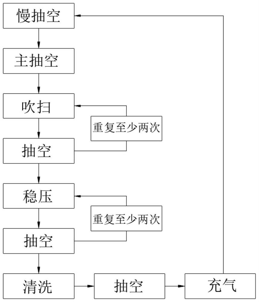
[0039] This embodiment provides a furnace tube cleaning method, the furnace tube cleaning method is as follows figure 1 shown, including the following steps:

[0040] (1) Perform slow evacuation and main evacuation in sequence in the furnace tube. The evacuation time of the slow evacuation is 120s. After the slow evacuation, the vacuum degree in the furnace tube is 1520Pa; The vacuum in the tube is 30Pa;

[0041] (2) Use nitrogen to purge the furnace tube, the nitrogen flow rate is 500sccm, and the purge temperature is 420°C; after the purge is completed, the furnace tube is evacuated, and the vacuum degree in the furnace tube is evacuated to 30Pa to complete a purge Evacuation operation; then repeat the purge and evacuation operation 3 times, the time of each purge is controlled at 200s, and the total duration of the purge during the entire purge and evacuation process is controlled at 10min;

[0042] (3) After the purging and evacuation operation cycle is completed, after ...

Embodiment 2

[0046] This embodiment provides a furnace tube cleaning method, the furnace tube cleaning method is as follows figure 1 shown, including the following steps:

[0047] (1) Perform slow evacuation and main evacuation in sequence in the furnace tube. The evacuation time of the slow evacuation is 140s. After the slow evacuation, the vacuum degree in the furnace tube is 1000Pa; The vacuum in the tube is 23Pa;

[0048] (2) Use nitrogen to purge the furnace tube, the nitrogen flow rate is 1000sccm, and the purge temperature is 450°C; after the purge is completed, the furnace tube is evacuated, and the vacuum degree in the furnace tube is evacuated to 23Pa to complete a purge Evacuation operation; then repeat the purge and evacuation operation 6 times, the time of each purge is controlled at 100s, and the total duration of the purge during the entire purge and evacuation process is controlled at 10min;

[0049] (3) After the purging and evacuation operation cycle is completed, after...

Embodiment 3

[0053] This embodiment provides a furnace tube cleaning method, the furnace tube cleaning method is as follows figure 1 shown, including the following steps:

[0054] (1) Perform slow evacuation and main evacuation in sequence in the furnace tube. The evacuation time of the slow evacuation is 160s. After the slow evacuation, the vacuum degree in the furnace tube is 800Pa; The vacuum in the tube is 20Pa;

[0055] (2) Use nitrogen to purge the furnace tube, the nitrogen flow rate is 1600sccm, and the purge temperature is 500°C; after the purge is completed, the furnace tube is evacuated, and the vacuum degree in the furnace tube is evacuated to 20Pa to complete a purge Evacuation operation; then repeat the purge and evacuation operation 6 times, the time of each purge is controlled at 120s, and the total duration of the purge during the entire purge and evacuation process is controlled at 12min;

[0056] (3) After the purging and evacuation operation cycle is completed, after ...


PUM


Abstract

The invention provides a furnace tube cleaning method which comprises the following step (I) of purging and evacuating a furnace tube in sequence, completing one-time purging and evacuating operation, and repeating the purging and evacuating operation for at least two times; the step (II) of maintaining the furnace tube for a period of time after the pressure in the furnace tube is stabilized, then evacuating the furnace tube, completing one-time stabilized pressure evacuating operation, and repeating the stabilized pressure evacuating operation for at least two times; and the step (III) of cleaning, evacuating and inflating the furnace tube in sequence to finish the cleaning work of the furnace tube. When the furnace tube cleaning method provided by the invention is used for cleaning the furnace tube used for many times, and a good dust falling effect can be obtained; dust in the furnace can be effectively prevented from being adhered to the surface of materials in the working process of the furnace tube, and the probability of black spots and hard spots occurred to the surface of the materials is reduced.

Description

technical field [0001] The invention belongs to the technical field of furnace tube cleaning and relates to a furnace tube cleaning method. Background technique [0002] PECVD, that is: plasma enhanced chemical vapor deposition. PECVD uses microwave or radio frequency to ionize the gas containing the constituent atoms of the film, and locally forms plasma, which is highly chemically active and easy to react, and deposits the desired film on the substrate. In order to enable the chemical reaction to proceed at a lower temperature, the activity of the plasma is used to promote the reaction, so this CVD is called plasma-enhanced chemical vapor deposition. [0003] In the production process of solar photovoltaic cells, the graphite boat is used as a carrier silicon wafer to run the coating process in the PECVD furnace tube, and a layer of SiN is also deposited on the surface of the graphite boat at the same time. x Dielectric film. After the number of graphite boat operations...

Claims


Application Information

Patent Timeline
IPC IPC(8): C23C16/44C23C16/50B08B9/032B08B9/035
CPCB08B9/0328B08B9/035C23C16/4405C23C16/4408C23C16/50
Inventor 雷丽茶赵颖任勇何悦
Owner HENGDIAN GRP DMEGC MAGNETICS CO LTD
Why Eureka
Try Eureka