A solar radio observation instrument, system and method

A technology for solar radio and observation instruments, applied in the field of solar radio observation, can solve problems such as weak interference suppression capability, complex structure, and many computing units, and achieve the effects of reducing FPGA resource consumption, improving sensitivity, and saving costs

Active Publication Date: 2022-05-31
SHANDONG UNIV
View PDF18 Cites 0 Cited by
  • Summary
  • Abstract
  • Description
  • Claims
  • Application Information

AI Technical Summary

Problems solved by technology

Although the structure of this method is simple, the monitoring results are easily affected by the surrounding environment, interference, and atmospheric turbulence. The system sensitivity is low and the ability to suppress interference is weak.
[0004] Moreover, when the existing solar radio 15-40GHz observation scheme performs amplitude calibration and phase compensation, the front end is mostly used to inject the calibration component into the channel, and the phase calculation and compensation are performed at the back end, as disclosed in the patent application number: 202010498823.7 A phased array transmission calibration device and method. Although the method can calculate and compensate the amplitude and phase, there are many calculation units and the calculation is complicated; the patent application number: 201911305600.8 discloses a method to improve the amplitude and phase consistency of the broadband frequency conversion receiving module The circuit, the result of this circuit adopts multi-stage frequency mixing and calibration, the structure is complex

Method used


Image

  • A solar radio observation instrument, system and method
  • A solar radio observation instrument, system and method
  • A solar radio observation instrument, system and method

Examples


Embodiment 1

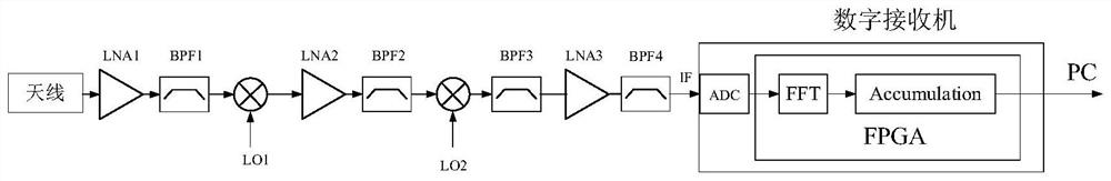
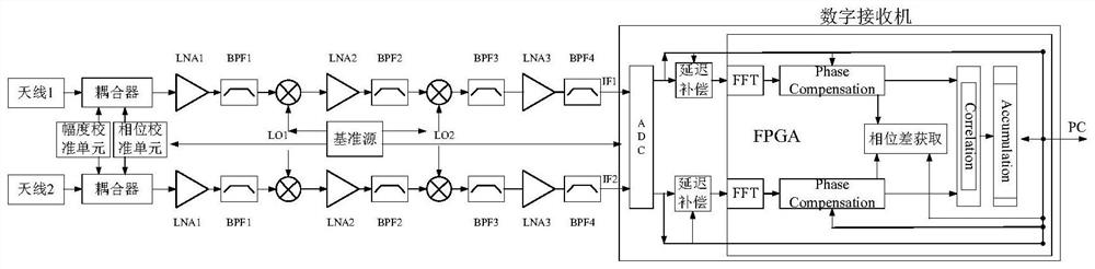
[0032] At present, the solar radio 15-40GHz observation scheme adopts the superheterodyne frequency conversion sampling processing structure, such as figure 1 As shown in Fig. 1, the sensitivity is low and the ability to suppress interference is weak, so on the basis of conventional broadband solar radio spectrum observation, an additional two-element coherent observation equipment is built. The output spectrum and radiation intensity of the element interference can be complementary to the conventional full-frequency observation to form data, wherein the additionally built two-element coherent observation equipment is a solar radio observation instrument disclosed in this embodiment, such as figure 2 shown, including:

[0033] Two antennas, each antenna is connected to the main antenna circuit through a coupler, both the main antenna circuits are connected to the digital receiver, the two couplers are connected to the digital receiver through the amplitude calibration unit an...

Embodiment 2

[0054] In this embodiment, a solar radio observation system is disclosed, including a conventional spectrum observer connected by a single antenna, an antenna main circuit and a digital receiver, and a solar radio observation instrument disclosed in Embodiment 1.

[0055] Among them, the structure of the conventional spectrum observer is as follows figure 1 As shown, the main circuit structure of the antenna of a conventional spectrum observer is the same as that of a solar radio observation instrument, including amplifier I, filter I, mixer I, amplifier II, filter II, Mixer II, filter III, amplifier III and filter IV, amplifier I is connected with the coupler, and filter IV is connected with the digital receiver.

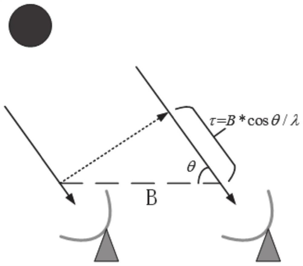
[0056] A solar radio observation system disclosed in this embodiment performs coherent observation on several points in the broadband observation while using conventional observation, such as figure 2 As shown, a single turntable and two antennas are used to perf...

Embodiment 3

[0058] In this embodiment, a solar radio observation method is disclosed, using a solar radio observation instrument disclosed in Embodiment 1, including:

[0059] Receive solar radio signals through two antennas respectively;

[0060] The two solar radio signals are sent to the digital receiver through the main antenna of the antenna to form two time-domain data;

[0061] Send the two time domain data to the host computer, and the host computer calculates the time domain delay of the two time domain data;

[0062] The time-domain delay is sent to the digital receiver to perform delay compensation on the two time-domain data.

[0063] Further, it also includes amplitude calibration. During the amplitude calibration, the digital receiver receives the amplitude calibration instruction sent by the upper computer, and controls the amplitude calibration unit to inject the amplitude calibration signal into the two antenna main circuits through the coupler, and the amplitude calibra...


PUM


Abstract

The present disclosure discloses a solar radio observation instrument, system and method, comprising: two antennas, each of which is connected to the antenna main circuit via a coupler, both antenna main circuits are connected to a digital receiver, and the two couplers The amplitude calibration unit and the phase calibration unit are connected to the digital receiver, and the digital receiver is connected to the host computer; two antennas are used to receive solar radio signals, and the two radio signals are received by the digital receiver after passing through the antenna main circuit to form two time For the data in the two time domains, the host computer calculates the time domain delay of the two time domain data, and sends the time domain delay to the digital receiver for delay compensation of the two time domain data. Eliminate the electromagnetic wave delay of solar radio through a single turntable and dual antennas, and the host computer calculates the compensation factor and sends the FPGA corresponding compensation to achieve real-time compensation while reducing FPGA resource consumption.

Description

technical field [0001] The invention relates to the technical field of solar radio observation, in particular to a solar radio observation instrument, system and method. Background technique [0002] The statements in this section merely provide background information related to the present disclosure and do not necessarily constitute prior art. [0003] At present, the solar radio 15-40GHz observation scheme adopts the superheterodyne frequency conversion sampling processing structure, such as figure 1 As shown in the figure, the collected solar radio high-frequency signal is down-converted to a low-IF signal, which is collected by an analog-to-digital converter ADC, and then subjected to fast Fourier transform to form a graph from the host computer spectrum. Although this method has a simple structure, the monitoring results are easily affected by the surrounding environment, interference and atmospheric turbulence, the system sensitivity is low, and the ability to suppre...

Claims


Application Information

Patent Timeline
Patent Type & Authority Patents(China)
IPC IPC(8): G01R29/08G01R35/00
CPCG01R29/0857G01R29/0814G01R29/0892G01R35/005Y02A90/10
Inventor 严发宝尚自乾许丙强张园园张磊陈耀武昭苏艳蕊路光
Owner SHANDONG UNIV
Why Eureka
Try Eureka