A feeder automatic on-site automatic test method and system

An automatic test system and feeder automation technology, applied in the direction of detecting faults and fault locations according to conductor types, can solve the problem of not being able to determine whether the coordination of multiple feeder terminals meets the requirements of system operation, unable to explain the behavior of the tested feeder terminals, and no Problems such as injected fault current and voltage are given to achieve the effect of reliable test results, comprehensive test and reduced requirements

Active Publication Date: 2021-11-16
北京天能继保电力科技有限公司
View PDF8 Cites 0 Cited by
  • Summary
  • Abstract
  • Description
  • Claims
  • Application Information

AI Technical Summary

Problems solved by technology

[0002] The existing test method is that multiple relay protection instruments inject normal current and voltage into multiple feeder automation terminals; one of the relay protection instruments injects fault current and voltage into a feeder automation terminal to generate a preset switch value, and the preset switch The logic of the quantity is the preset logic rule. This method needs to set the standard fault in advance, but does not give the specific method of injecting the fault current and voltage; only one relay protector injects the fault current and voltage into one feeder automation terminal, and the power distribution When a fault occurs in the network system, fault current will flow through multiple feeder terminals on the fault branch. The electrical quantities in several working states of the test sequence in the above method are artificially set, which is not the actual failure of the system where the feeder terminal under test is located. Even if the tested feeder terminal passes the test, it does not mean that the tested feeder terminal is still correct when the system fails once in actual operation.
The above test plan is compiled according to the specific function type of the feeder automation of a feeder terminal, without testing the mutual influence of multiple feeder terminals operating simultaneously in the system, it is impossible to determine whether the cooperation of multiple feeder terminals in the system meets the requirements of the system operation Require

Method used


Image

  • A feeder automatic on-site automatic test method and system
  • A feeder automatic on-site automatic test method and system
  • A feeder automatic on-site automatic test method and system

Examples


Embodiment Construction

[0061] The principles and features of the present invention will be described below in conjunction with the accompanying drawings, and the examples given are only used to explain the present invention, and are not intended to limit the scope of the present invention.

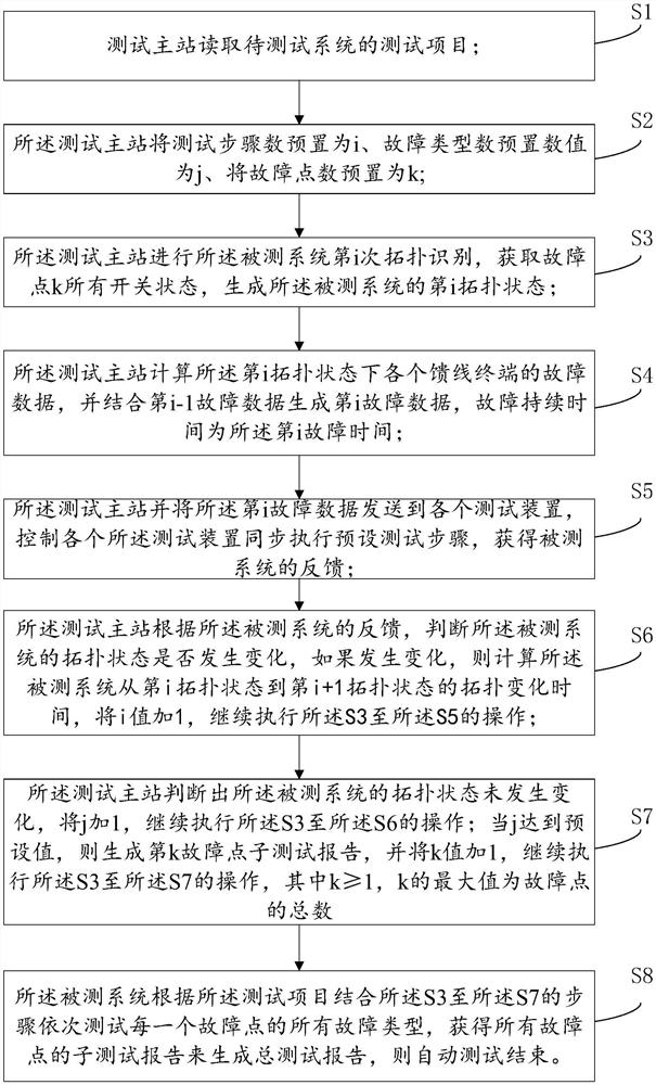
[0062] like figure 1 As shown, a kind of feeder automatic on-site automatic testing method provided by the embodiment of the present invention includes:

[0063] S1, the test master station reads the test items of the system to be tested, including: fault point, fault type and fault duration;

[0064] S2, the test master station presets the number of test steps as i, the number of fault types as j, and the number of fault points as k;

[0065] S3, the test master station performs the i-th topology identification of the system under test, obtains all switch states of the fault point k, and generates the i-th topology state of the system under test;

[0066] S4, the test master station calculates the fault data ...


PUM


Abstract

The invention discloses a feeder automation site automatic testing method and system, relating to the field of power distribution automation. The method includes: during the test process, according to the test data of the previous step, the topology change time obtained from the feeder terminal action behavior feedback in the system under test after the test execution of the previous step, and the data calculated in this step. Data synthesis, generating test data for the current step, and controlling the automatic testing until the behavior of the system under test no longer changes. The test method of this program does not need to pre-compile a variety of test programs and artificially set the sequence of working conditions. The test program is automatically generated according to the feedback of the action behavior of the feeder terminal in the system under test, and the automatic function of the feeder can be checked. Multiple in the system. Coordination inspection between feeder terminals reduces the requirements for testers, the on-site test process is simple, the test results are reliable, and the test is comprehensive.

Description

technical field [0001] The invention relates to the field of power distribution automation, in particular to a field automatic test method and system for feeder automation. Background technique [0002] The existing test method is that multiple relay protection instruments inject normal current and voltage into multiple feeder automation terminals; one of the relay protection instruments injects fault current and voltage into a feeder automation terminal to generate a preset switch value, and the preset switch The logic of the quantity is the preset logic rule. This method needs to set the standard fault in advance, but does not give the specific method of injecting the fault current and voltage; only one relay protector injects the fault current and voltage into one feeder automation terminal, and the power distribution When a fault occurs in the network system, fault current will flow through multiple feeder terminals on the fault branch. The electrical quantities in sever...

Claims


Application Information

Patent Timeline
Patent Type & Authority Patents(China)
IPC IPC(8): G01R31/08
CPCG01R31/086
Inventor 陈成李春久庄乾鑫韩峰张发俊刘芬杨秀英翟永成
Owner 北京天能继保电力科技有限公司
Why Eureka
Try Eureka