Magnetic sensor

A magnetic sensor and magnetic induction technology, applied in the field of magnetic sensors, can solve the problems of weak detection ability and limited usage scenarios, and achieve the effect of easy integration

Active Publication Date: 2021-06-25
LOMARE CHIP TECH CHANGZHOU CO LTD
View PDF7 Cites 0 Cited by
  • Summary
  • Abstract
  • Description
  • Claims
  • Application Information

AI Technical Summary

Problems solved by technology

[0005] Due to structural limitations, existing magnetoelectric sensors have weak detection capabilities for environments with low magnetic field strength, which limits their application scenarios.

Method used


Image

  • Magnetic sensor
  • Magnetic sensor
  • Magnetic sensor

Examples


Embodiment 1

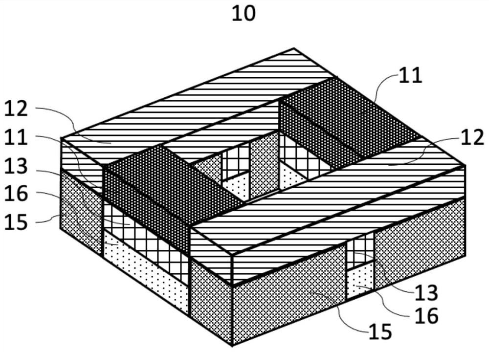
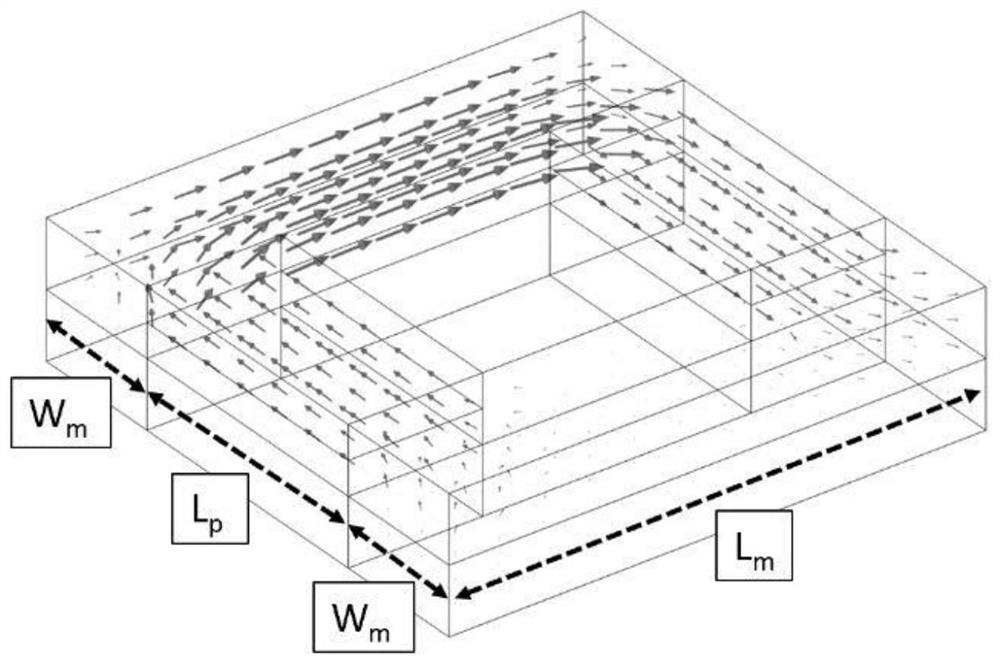
[0069] refer to Figure 1 to Figure 5 , respectively show the structure, working principle and magnification of the magnetic sensor 10 in the first embodiment. In this embodiment, the first magnetostrictive element and the second magnetostrictive element are respectively arranged on the normal side of the first piezoelectric element and the second piezoelectric element, and the first magnetostrictive element, the second magnetostrictive The element, the first piezomagnetic element and the second piezomagnetic element are arranged on the same horizontal layer, thereby forming a rectangular magnetic induction layer, and the rectangular induction layer has the same length and width (such as figure 2 shown), that is, in specific design, the length of the first magnetostrictive element and the second magnetostrictive element can be configured as L m , whose width is W m , the length of the first piezomagnetic element and the second piezomagnetic element is L p , so that L m = ...

Embodiment 2

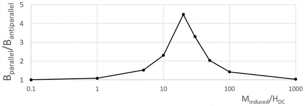
[0074] In order to further increase the measured magnetic field H DC The magnification of the sensor, which extends the sensitivity of the sensor to lower magnetic fields, can increase the L m , while reducing L p and W m . Specifically, see Figure 6-9 , respectively show the structure and magnification schematic diagram of the magnetic sensor 10 of the second embodiment. In this embodiment, the same as the first embodiment, the first magnetostrictive element and the second magnetostrictive element are respectively arranged on the first piezoelectric On the normal side of the element and the second piezomagnetic element, the first magnetostrictive element, the second magnetostrictive element, the first piezomagnetic element and the second piezomagnetic element are arranged on the same horizontal layer to form a rectangular magnetic induction layer , in addition, also has a magnetostrictive element 14, preferably can be made of high permeability material (with low or negli...

Embodiment 3

[0080] refer to Figure 10-12 , respectively show the structure and magnification schematic diagram of the magnetic sensor 10 of the third embodiment. In this embodiment, the measured magnetic field H DC The highest magnification and simplified structure. Specifically, the first magnetostrictive element and the second magnetostrictive element are respectively arranged on the same side of the first piezoelectric element and the second piezoelectric element, and the first magnetostrictive element is arranged on the first piezoelectric element, and the second Two magnetostrictive elements are arranged on the second piezoelectric element to form a magnetic induction strip. Compared with the first and second embodiments above, the magnetic circuit is replaced by two "vertical" magnetic circuits. The bottom of the circuit is composed of a piezoelectric component 11, and its induced magnetization is controlled by the piezoelectric component 13 below. Readings were taken on both sid...


PUM

PropertyMeasurementUnit
thicknessaaaaaaaaaa
thicknessaaaaaaaaaa
lengthaaaaaaaaaa

Abstract

The invention provides a magnetic sensor which comprises a piezomagnetic assembly comprising a first piezomagnetic element and a second piezomagnetic element, a magnetostriction assembly comprising a first magnetostriction element and a second magnetostriction element, and a piezoelectric assembly comprising a first piezoelectric element, a second piezoelectric element, a third piezoelectric element and a fourth piezoelectric element. The first piezoelectric element and the second piezoelectric element are electrically connected to the power supply circuit to generate first deformation, and the first deformation is applied to the first piezomagnetic element and the second piezomagnetic element to generate an alternating magnetic field HAC. The alternating magnetic field HAC and the measured magnetic field HDC are superposed to form a magnetic loop, the first magnetostriction element forms second deformation, the second magnetostriction element forms third deformation, the second deformation and the third deformation respectively form first potential and second potential on the third piezoelectric element and the fourth piezoelectric element, and the magnetic sensor calculates the magnetic field intensity of the measured magnetic field HDC. Therefore, the magnetic sensor can be applied to magnetic fields as low as about 10 pT, and the application scene can be expanded to drawing of magnetocardiograms or magnetoencephalograms.

Description

technical field [0001] The invention relates to the field of sensor equipment, in particular to a magnetic sensor. Background technique [0002] Sensor technology has become an important technology that restricts modern progress, and the development of sensors has gone through a development process from common to high precision, expensive to popular, and the development of cheap, high-precision, low-power sensors has become the current development of sensors. a big trend. [0003] As one of the sensor categories, the magnetic sensor plays an increasingly important role in the development of modern science and technology, and its reliability and flexibility make it more and more widely used. In terms of types, magnetic sensors can be divided into: induction coil type (Search coil), Hall effect type (Hall effect), magnetoresistance type (AMR or GMR), magnetic tunnel type (MTJ or SDJ), magneto-optical type ( Magneto-optical), Optically pumped, Magneto-diode, Magneto-transisto...

Claims


Application Information

Patent Timeline
Patent Type & Authority Applications(China)
IPC IPC(8): G01R33/02A61B5/243A61B5/245
CPCG01R33/02G01R33/0011G01R33/0094G01R33/0029G01R33/0082H10N35/00H10N35/85H10N35/101
Inventor 简·泽曼安德烈·保罗·米哈伊邹斌
Owner LOMARE CHIP TECH CHANGZHOU CO LTD
Why Eureka
Try Eureka