Containment built-in efficient heat exchanger adopting self-flowing type air suction system

A heat exchanger and containment technology, which is applied in the field of high-efficiency heat exchangers built into the containment to achieve the effects of increasing the mass share, inhibiting deposition, and enhancing the condensation heat transfer capacity

Pending Publication Date: 2021-06-25
HARBIN ENG UNIV
View PDF5 Cites 0 Cited by
  • Summary
  • Abstract
  • Description
  • Claims
  • Application Information

AI Technical Summary

Problems solved by technology

[0006] During the development of the accident, the PCCS will gradually dissipate the heat in the containment during the long-term operation. During the operation of the PCCS, a large amount of steam will condense on the surface of the heat exchanger inside the containment At the same time, a large amount of non-condensable gas will accumulate on the outer surface of the heat exchanger inside the containment, so that a gas film will be formed on the outer surface of each heat exchange tube to inhibit steam condensation and heat transfer. The published patents have not formed an effective solution to this problem

Method used


Image

  • Containment built-in efficient heat exchanger adopting self-flowing type air suction system
  • Containment built-in efficient heat exchanger adopting self-flowing type air suction system
  • Containment built-in efficient heat exchanger adopting self-flowing type air suction system

Examples


Embodiment Construction

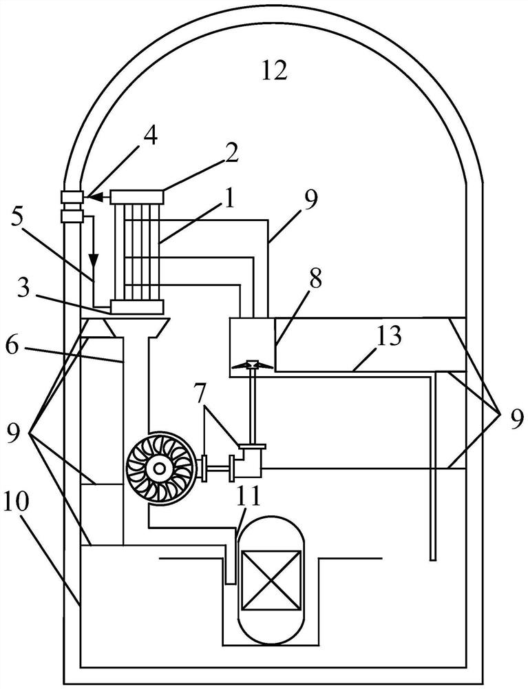
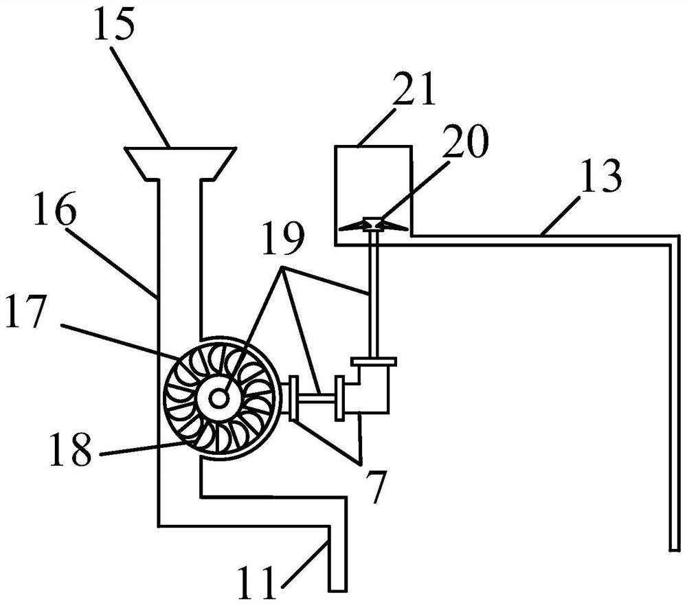
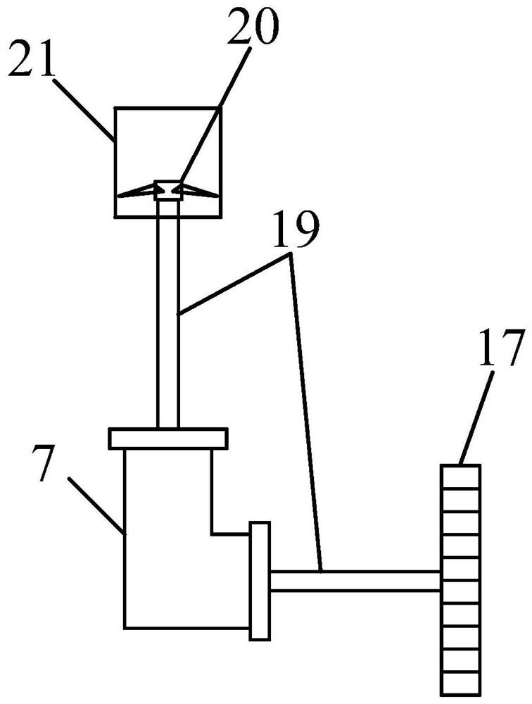
[0026] The present invention will be further described in detail below in conjunction with the accompanying drawings and specific embodiments.

[0027] to combine figure 1 -5. The present invention provides a high-efficiency heat exchanger built into the containment using a self-flowing suction system. Mainly include containment built-in heat exchanger 1, heat exchanger outlet header 2, heat exchanger inlet header 3, upper pipe section 4, lower pipe section 5, water delivery structure 6, gear steering box 7, suction structure 8, support Column 9, containment inner wall surface 10, drain pipe 11, containment gas space 12, exhaust pipe 13, suction pipe 14.

[0028] The invention discloses a high-efficiency heat exchanger built in a containment using a self-flowing suction system, including a heat exchanger inlet header, a heat exchange tube, a heat exchanger outlet header, and a self-flowing suction system. The tube bundles of the heat exchanger inside the containment are pref...


PUM


Abstract

The invention provides a containment built-in efficient heat exchanger adopting a self-flowing type air suction system, which mainly comprises a heat exchanger inlet header, a heat exchange tube, a heat exchanger outlet header and the self-flowing type air suction system, and the self-flowing type air suction system comprises a water delivery structure, a water bucket type water wheel, an air suction structure, a drain pipe, an exhaust pipe and a gear steering box. The self-flow type air suction system can convert water flow potential energy of steam condensation into jet flow kinetic energy to drive the air suction impeller to rotate to generate suction force, so that a non-condensable gas film near the heat exchange pipe is sucked away, and the steam can be better condensed and exchange heat on the outer surface of the heat exchange pipe. The heat in the containment can be efficiently taken away when a crevasse accident occurs in the containment, a non-condensable gas film can be effectively thinned by utilizing the self-flow type air suction system, the contact between steam and a pipe bundle is enhanced, efficient heat transfer is realized, efficient temperature and pressure reduction in the containment under the accident condition can be ensured, and the safety of the containment is ensured. The safety of the containment is enhanced; and a feasible scheme is provided for reducing the construction cost of the containment.

Description

technical field [0001] The invention relates to high-efficiency heat exchange equipment for a passive containment cooling system, and specifically refers to a high-efficiency heat exchanger built in a containment that adopts a self-flowing suction system. Background technique [0002] The 21st century is an important stage of human development, and it is also a stage of shortage of conventional energy. Because of its clean and efficient characteristics, nuclear energy has attracted people's attention since its discovery. With the continuous development and maturity of nuclear energy technology, nuclear energy has gradually become a new major energy source. Its high energy density, clean and efficient characteristics make it more and more widely used. [0003] While nuclear energy brings clean and efficient energy to mankind, it also brings many risks. With the development of nuclear power technology, more and more attention has been paid to the safety of nuclear power plant...

Claims


Application Information

Patent Timeline
IPC IPC(8): G21C15/18G21C15/14G21C15/02G21C15/243G21C15/26
CPCG21C15/18G21C15/14G21C15/02G21C15/243G21C15/26Y02E30/30
Inventor 曹夏昕周书航曹博洋边浩志丁铭邢继孙中宁张楠孟兆明李伟
Owner HARBIN ENG UNIV
Why Eureka
Try Eureka