
Chip mounting method and chip mounting device

A chip mounting and chip technology, which is applied in the field of chip mounting methods and devices, can solve the problems of chip angle offset and influence, and achieve the effects of reducing errors, reducing angle offset, and improving alignment accuracy.

Active Publication Date: 2021-06-25
东莞普莱信智能技术有限公司
View PDF9 Cites 3 Cited by
  • Summary
  • Abstract
  • Description
  • Claims
  • Application Information

AI Technical Summary

Problems solved by technology

[0006] Aiming at the problem that the chip mounting accuracy is easily affected by the chip angle offset in the prior art, the present invention provides a chip mounting method and device

Method used


Image

  • Chip mounting method and chip mounting device
  • Chip mounting method and chip mounting device
  • Chip mounting method and chip mounting device

Examples


Embodiment 1

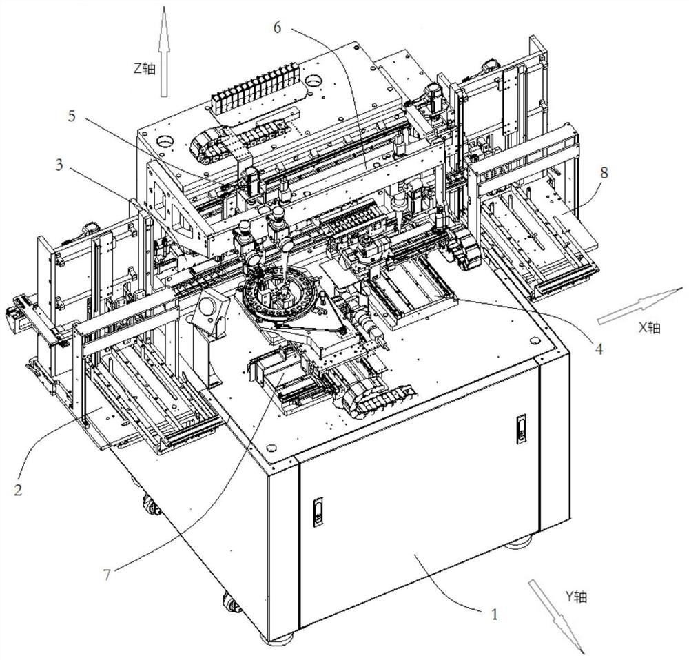
[0036] by Figure 1 to Figure 5 A chip mounting device is shown as an example, and a chip mounting method is described.

[0037] A chip mounting method is characterized in that, comprising the following steps:

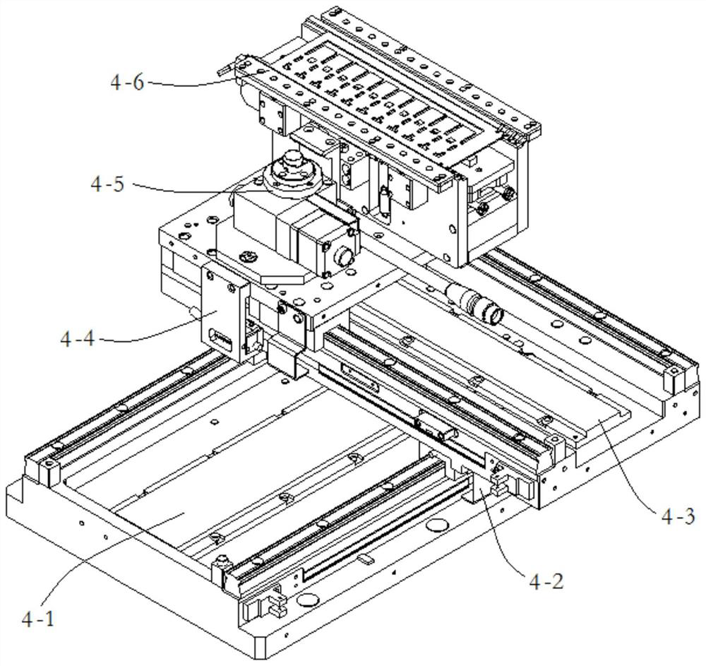
[0038] S1: sending the substrate into the alignment welding device 4 . In this embodiment, the substrate is picked up from the substrate loading device 2 by the substrate feeding device 3, and the substrate is sent to the alignment welding device 4, and the substrate is put into the chip bonding platform 4-6.

[0039] S2: placing the chip on the chip positioning device 7 .

[0040] S3: The camera positioning device 6 identifies the positioning coordinates, and the chip positioning device 7 adjusts the position and angle of the chip to the positioning coordinates. In this embodiment, the chip positioning vision system 6-2 in the camera positioning device 6 is arranged on the upper side of the chip positioning device 7 through the installation frame 6-1, and the chip ...

Embodiment 2

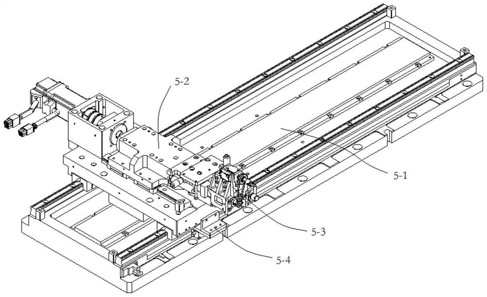
[0058] like figure 1 As shown, the present invention also provides a chip mounting device, including a substrate loading device 2, a substrate feeding device 3, an alignment welding device 4, a chip feeding device 5, a chip positioning device 7, a camera positioning device 6, a blanking device Device 8, the output end of the substrate feeding device 2 is connected to the substrate input end of the alignment welding device 4 through the substrate feeding device 3, and the output end of the chip positioning device 7 is connected to the chip input end of the alignment welding device 4 through the chip feeding device 5 connection, the output end of the alignment welding device 4 is connected to the input end of the blanking device 8 through the substrate feeding device 3, and the chip feeding device 5, the chip positioning device 7, and the alignment welding device 4 are respectively provided with linear motors, so A grating sensor is fixed on the linear motor, and the camera posi...


PUM


Abstract

The invention provides a chip mounting method and a chip mounting device. According to the chip mounting method and the chip mounting device of the invention, angle positioning is performed on a chip before welding of the chip, so that angle deviation between the chip and a substrate is reduced; a linear motor is used for adjusting the positions of the chip and the substrate, and a grating encoder is used for controlling the movement of the linear motor, so that errors caused by mechanical transmission are reduced; and a positioning position and a welding position are arranged at the visual center of a camera positioning device, so that the influence of motion errors on the chip mounting precision caused by the influence of heat generated by mechanical vibration and long-time operation of equipment on the motion precision of the equipment in the chip mounting process is reduced. According to the chip mounting method and the chip mounting device of the invention, the chip mounting precision can be effectively improved.

Description

technical field [0001] The invention relates to the technical field of manufacturing semiconductor devices, relates to the mounting of semiconductor chips, and in particular to a chip mounting method and device. Background technique [0002] The existing semiconductor chip mounting and welding technology generally constructs an open-loop or closed-loop motion control system through components such as screw rods, guide rails, servo motors, and cameras, picks up the chip and transports it to the mounting and welding position, and solders the chip on the substrate. . Among them, the positioning of the chip and the substrate is an important link to ensure the accuracy of chip placement. [0003] Document CN109616430B discloses a chip mounting recognition system and method, wherein the system includes a photographing device, a substrate and an adsorption device, the photographing device is located above the substrate, the substrate is used to mount chips, and the adsorption devi...

Claims


Application Information

Patent Timeline
Patent Type & Authority Applications(China)
IPC IPC(8): H01L21/50H01L21/68H01L21/67
CPCH01L21/50H01L21/681H01L21/67121Y02P70/50
Inventor 孟晋辉何海东李南庆李帝杰
Owner 东莞普莱信智能技术有限公司
Learn More