
Laser reflow welding robot placing table with fixing function

A technology of reflow soldering and fixed functions, which is applied in the field of placing tables, can solve problems such as unfavorable use by operators, safety, and inconvenience for operators to work, and achieve the effect of avoiding maintenance work from being blocked, facilitating use, and convenient operation

Inactive Publication Date: 2021-06-29
武汉诺克萨斯科技有限公司
View PDF0 Cites 2 Cited by
  • Summary
  • Abstract
  • Description
  • Claims
  • Application Information

AI Technical Summary

Problems solved by technology

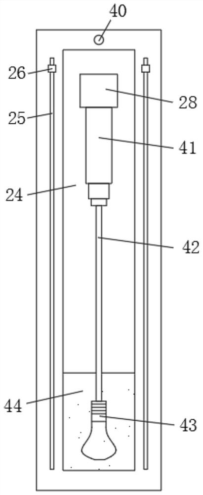
[0005] The technical problem to be solved by the present invention is to overcome the existing defects and provide a laser reflow welding robot placement table with fixed functions, so as to solve the problem that some welding robots in the background technology lack special placement tables, which makes it inconvenient to place the robot. It is easy to cause the robot to be fixed not stable enough, and there are potential safety hazards during work, and when the welding robot fails to be repaired, and the illumination is not enough, the operator needs to hold the light for a long time to repair, which is likely to cause inconvenience to the operator, and some The lighting device is fixed on other objects, it is inconvenient to adjust, and it is not conducive to the use of the operator

Method used


Image

  • Laser reflow welding robot placing table with fixing function
  • Laser reflow welding robot placing table with fixing function
  • Laser reflow welding robot placing table with fixing function

Examples


Embodiment Construction

[0030] The following will clearly and completely describe the technical solutions in the embodiments of the present invention with reference to the accompanying drawings in the embodiments of the present invention. Obviously, the described embodiments are only some, not all, embodiments of the present invention. Based on the embodiments of the present invention, all other embodiments obtained by persons of ordinary skill in the art without making creative efforts belong to the protection scope of the present invention.

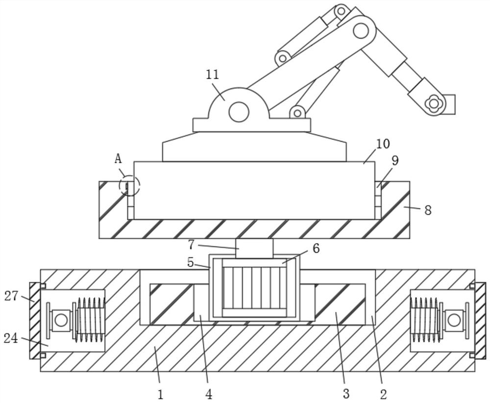
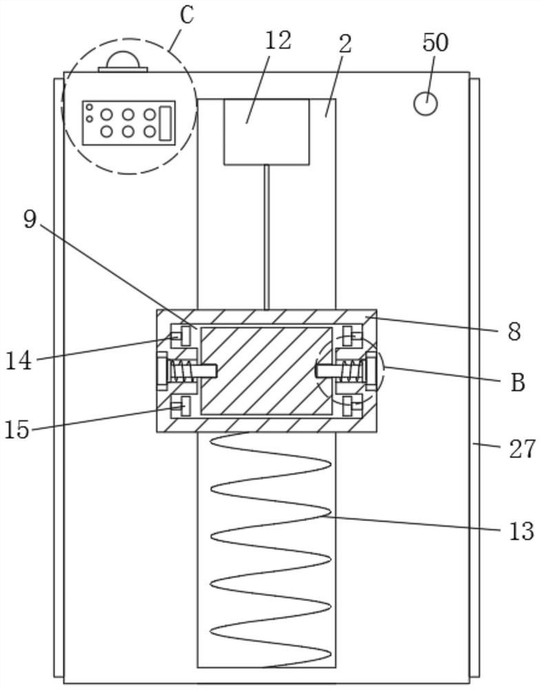
[0031] see Figure 1-8, the present invention provides a technical solution: a laser reflow welding robot placement table with a fixed function, including a fixed placement table 1, a fixed plate 8 and a robot control base 10, the upper surface of the robot control base 10 and the bottom surface of the robot body 11 Fixedly connected, the upper surface of the fixed plate 8 is provided with an I-shaped groove 9, the fixed plate 8 is connected with the bottom en...


PUM


Abstract

The invention discloses a laser reflow welding robot placing table with a fixing function. The laser reflow welding robot placing table with the fixing function comprises a fixed placing table, a fixing plate and a robot control base; the upper surface of the robot control base is fixedly connected to the bottom surface of a robot main body; an I-shaped groove is formed in the upper surface of the fixing plate; the fixing plate is connected to the bottom end of the robot control base in an inserted mode through the I-shaped groove; third grooves are formed in the two sides of the fixing plate; and one end of a first insertion rod is arranged in each third groove. According to the invention, the fixing plate is arranged above the fixed placing table, the fixing plate is fixedly connected to the robot control base through the first insertion rods on the two sides, so that the fixing plate and the robot control base are stably fixed, and the safety problem caused by unstable fixing during work of the robot body is avoided; and the robot body and the robot control base can be detached and replaced by pulling out the first inserting rods, therefore, the operation is convenient, and the use is facilitated.

Description

technical field [0001] The invention belongs to a placement table, in particular to a laser reflow welding robot placement table with a fixed function. Background technique [0002] A welding robot is an industrial robot engaged in welding (including cutting and spraying). According to the definition of a standard welding robot in the International Organization for Standardization (ISO), an industrial robot is a multi-purpose, reprogrammable automatic control operation machine (Manipulator ), with three or more programmable axes, used in the field of industrial automation, in order to adapt to different purposes, the mechanical interface of the last axis of the robot, usually a connecting flange, can be connected to different tools or end effectors The welding robot is equipped with welding tongs or welding (cutting) guns on the flange of the final axis of the industrial robot, so that it can perform welding, cutting or thermal spraying. [0003] The welding robot mainly in...

Claims


Application Information

Patent Timeline
Patent Type & Authority Applications(China)
IPC IPC(8): B23K26/70B23K26/21B25J9/00B25J19/00
CPCB25J9/0009B25J19/00B23K26/21B23K26/70
Inventor 闫岩陈水鹏
Owner 武汉诺克萨斯科技有限公司
Learn More