Small space tether system unfolding brake mechanism adopting spinning shaft sleeve

A technology of a space tether system and a braking mechanism, which is applied to motor vehicles, space navigation equipment, space navigation aircraft, etc., can solve problems such as release failure, poor environmental adaptability, and complex structure, so as to improve reliability and realize Punctuality and the effect of improving economy

Active Publication Date: 2021-06-29
NORTHWESTERN POLYTECHNICAL UNIV
View PDF7 Cites 3 Cited by
  • Summary
  • Abstract
  • Description
  • Claims
  • Application Information

AI Technical Summary

Problems solved by technology

[0004] A lot of research has been done at home and abroad on the deployment and braking technology of the tether system. In 2007, TUI Corporation of the United States and the Space System Research Laboratory of Stanford University jointly developed a multi-cube satellite connected by a tether, and released it using a launch vehicle. In space, one of the pico-satellites has a 1km tether and a release mechanism. It is planned to deploy at a speed of 3m/s relative to the other two blocks. It is equipped with a passive brake device to prevent rebound, but somehow, TED A glitch occurred during the release, failing to generate enough thrust to unwind the tether on the reel, causing the release to fail, so that the original plan was to use the Gadget to slowly crawl on the tether after the tether was fully released t

Method used


Image

  • Small space tether system unfolding brake mechanism adopting spinning shaft sleeve
  • Small space tether system unfolding brake mechanism adopting spinning shaft sleeve
  • Small space tether system unfolding brake mechanism adopting spinning shaft sleeve

Examples


Embodiment Construction

[0034] The embodiments described below by referring to the figures are exemplary and are intended to explain the present invention and should not be construed as limiting the present invention.

[0035] In describing the present invention, it should be understood that the terms "center", "longitudinal", "transverse", "length", "width", "thickness", "upper", "lower", "front", " Orientation indicated by rear, left, right, vertical, horizontal, top, bottom, inside, outside, clockwise, counterclockwise, etc. The positional relationship is based on the orientation or positional relationship shown in the drawings, which is only for the convenience of describing the present invention and simplifying the description, rather than indicating or implying that the referred device or element must have a specific orientation, be constructed and operated in a specific orientation, Therefore, it should not be construed as limiting the invention.

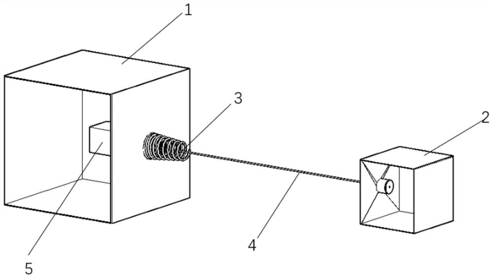
[0036] Such as figure 1 As shown, the paren...


PUM


Abstract

The invention discloses a small space tether system unfolding brake mechanism adopting a spinning shaft sleeve, and belongs to the technical field of space tether system equipment. The small space tether system unfolding brake mechanism comprises a small instrument cabin, and a spinning brake, a tether spool core, a tether calibration device, a high-strength tether, an unfolding length measurement module and an ejection module which are arranged in the small instrument cabin, the small instrument cabin is fixed on a mother satellite of the space tether system; the spinning brake restrains the axial displacement of the spinning shaft sleeve through the elastic force of a spring in the spinning brake, so that the unfolding motion of the high-strength tether is braked until the speed is zero; the tether spool core is used for winding a tether, and the unfolding length measuring module is used for guiding the tether and measuring the length and the speed of the tether; and the ejection module is used for control and signal processing of the whole mechanism. The elastic force of the compression spring is changed by changing the thread screwing length of the spinning brake, rotation of the spinning shaft sleeve along threads is restrained, and therefore the braking speed reduction effect of the tether is changed; the braking mechanism is effective in framework damping, low in space occupancy rate and reliable in release.

Description

technical field [0001] The invention belongs to the technical field of space tether system equipment, and in particular relates to a small-scale space tether system deploying braking mechanism using a spinning bushing. Background technique [0002] The space tether system is a new type of spacecraft composed of satellites, probes, manned spacecraft, rocket final stages or other aircraft connected by flexible tethers. Its unique structure and system characteristics can be applied to various space missions such as earth observation, space debris removal, payload delivery, artificial gravity, and space environment detection. Compared with traditional spacecraft, the space tether system has reusable , Strong flexibility and low cost. [0003] The tether used to connect the parent star and the child star is a key component of the tether system. The first stage of the space tether system is to deploy the tether. When the tether system is released in low-Earth orbit, it will unfol...

Claims


Application Information

Patent Timeline
IPC IPC(8): B64G1/64
CPCB64G1/648
Inventor 王长青孙佩杰李爱军郭永杨庶
Owner NORTHWESTERN POLYTECHNICAL UNIV
Why Eureka
Try Eureka