Automatic unblocking system and unblocking method for sampling hole of converter vaporization flue

A technology of vaporization flue and sampling hole, which is applied in the direction of manufacturing converters, improving process efficiency, and improving energy efficiency. It can solve problems such as poor working conditions of vaporization flue, blockage of sampling holes of detection devices, and difficulty in stable and reliable cleaning. , to achieve the effect of reducing maintenance, prolonging service life and ensuring stability

Active Publication Date: 2021-06-29
CHINA NAT HEAVY MACHINERY RES INSTCO
View PDF4 Cites 0 Cited by
  • Summary
  • Abstract
  • Description
  • Claims
  • Application Information

AI Technical Summary

Problems solved by technology

[0003] The purpose of the present invention is to overcome the deficiencies of the above-mentioned prior art, and provide an automatic system and method for clearing the sampling hole of the converter vaporization flue, which overcomes the poor working conditions and the detection of pressure in the vaporization flue in the prior art. The sampling hole of the device is often blocked, and the current conventional nitrogen and other purging devices are difficult to clean up stably and reliably

Method used


Image

  • Automatic unblocking system and unblocking method for sampling hole of converter vaporization flue

Examples


specific Embodiment approach

[0029] It should be noted that the structures, proportions, sizes, etc. shown in this specification are only used to cooperate with the content disclosed in the specification for the understanding and reading of those familiar with this technology, and are not used to limit the conditions for the implementation of the present invention , any modification of structure, change of proportional relationship or adjustment of size shall still fall within the scope covered by the technical content disclosed in the present invention without affecting the effect and purpose of the present invention. .

[0030] At the same time, terms such as "upper", "lower", "left", "right", "middle" and "one" quoted in this specification are only for the convenience of description and are not used to limit this specification. The practicable scope of the invention and the change or adjustment of its relative relationship shall also be regarded as the practicable scope of the present invention without...

Embodiment 1

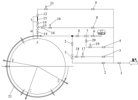
[0032] Such as figure 1As shown, the present invention discloses an automatic blocking removal system for the sampling hole of the converter vaporization flue, including a purge pipeline, a purge driving pipeline, a sampling driving pipeline, a sampling pipeline, a sampling hole control valve group, a needle driving pipeline, and a valve group Drive pipeline, needle 13 and control assembly, one end of the purge pipeline, purge drive pipeline, sampling drive pipeline, needle drive pipeline, valve group drive pipeline is respectively connected to the nitrogen input pipeline, and the other end of the purge pipeline is connected to the sampling pipeline, the other end of the purge driving pipeline is connected to the purge pipeline, the other end of the sampling driving pipeline is connected to the sampling pipeline, the other end of the needle driving pipeline is connected to the needle 13, and the other end of the valve group driving pipeline is connected to the sampling hole con...

Embodiment 2

[0036] preferred, such as figure 1 As shown, the sampling pipeline includes two sampling manual valves 6 and a sampling pneumatic valve 7, the two ends of the sampling pneumatic valve 7 are respectively connected to the sampling manual valve 6 through pipelines, and the other end of the sampling manual valve 6 is connected to the converter vaporization through a pipeline The flue sampling hole, another sampling manual valve 6, the other end is connected to a PT testing instrument through a pipeline.

[0037] preferred, such as figure 1 As shown, the sampling driving pipeline includes a sampling driving manual valve 4, a sampling driving solenoid valve 19 and a sampling driving cylinder 20, wherein one end of the sampling driving manual valve 4 is connected to the nitrogen main valve 1 of the nitrogen input pipeline through a pipeline, and the sampling driving manual valve 4 The other end is connected to the sampling drive solenoid valve 19 through the pipeline, and the other ...


PUM


Abstract

The invention discloses an automatic unblocking system and an unblocking method for a sampling hole of a converter vaporization flue. One end of a purging pipeline, one end of a purging driving pipeline, one end of a sampling driving pipeline, one end of a poking needle driving pipeline and one end of a valve group driving pipeline are respectively connected with a nitrogen input pipeline, the other end of the purging pipeline is connected with a sampling pipeline, the other end of the purging driving pipeline is connected with the purging pipeline, the other end of the sampling driving pipeline is connected with the sampling pipeline, the other end of the poking needle driving pipeline is connected with a poking needle, the other end of the valve group driving pipeline is connected with a sampling hole control valve group, the poking needle is opposite to the sampling hole control valve group, and the other end of the sampling hole control valve group is connected with a converter vaporization flue sampling hole; The poking needle, the sampling hole control valve set and the converter vaporization flue sampling hole are located on the same axis, one end of the sampling pipeline is connected with the converter vaporization flue sampling hole, the other end of the sampling pipeline is connected with a PT detection instrument, and the purging driving pipeline, the sampling driving pipeline, the poking needle driving pipeline and the valve set driving pipeline are electrically connected with a control assembly.

Description

technical field [0001] The invention belongs to the technical field of converter vaporization flue blockage removal, and in particular relates to an automatic blockage removal system and method for a sampling hole of a converter vaporization flue. Background technique [0002] Oxygen converter steelmaking flue gas is one of the main air pollutants produced in the production process of the converter steelmaking industry. The coal gas and iron-containing dust in the converter flue gas must be recovered and utilized. Since the temperature of the converter steelmaking flue gas is as high as 1600 degrees, The first process after the converter flue gas is generated is to use the vaporization cooling flue to cool down, and at the same time to recover the steam generated by heat exchange. In order to increase the amount of gas recovery and effectively and accurately control the speed of the fan in the system, devices such as pressure sensing are often installed on the flue. Due to ...

Claims


Application Information

Patent Timeline
Patent Type & Authority Applications(China)
IPC IPC(8): C21C5/46C21C5/40
CPCC21C5/4673C21C5/40Y02P10/25
Inventor 李永辉李新强边靖高璐吴量马莉莉
Owner CHINA NAT HEAVY MACHINERY RES INSTCO
Why Eureka
Try Eureka