Energy-saving and environment-friendly rail transit rapid cleaning device
A technology for rail transit, energy saving and environmental protection, applied in track cleaning, cleaning methods, construction, etc., can solve the problems of easy re-icing, cleaning efficiency, hidden dangers of train safety, inability to collect ice and snow in a centralized manner, and achieve the effect of fast heat conduction
- Summary
- Abstract
- Description
- Claims
- Application Information
AI Technical Summary
Problems solved by technology
Method used
Image
Examples
Embodiment 1
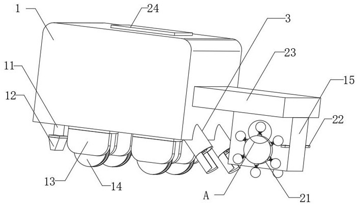
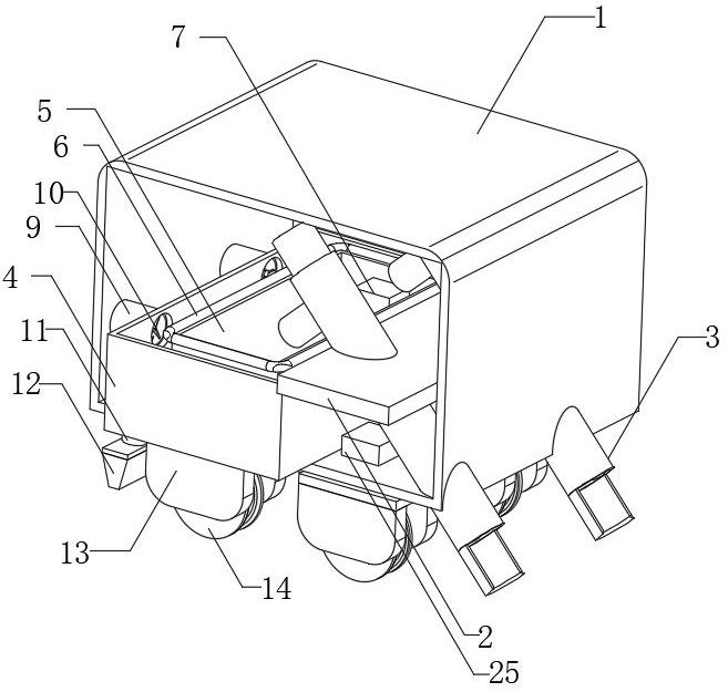
[0026] see Figure 1-7 , the present invention provides a technical solution: an energy-saving and environment-friendly rapid cleaning device for rail transit, including a box body 1, a fixing plate 2 is fixedly installed inside the box body 1, and two fixed plates are fixedly connected inside the box body 1 through the fixing plate 2 A feeding assembly 3, the feeding assembly 3 extends to the outside of the casing 1, the feeding assembly 3 includes a side opening feeding barrel 301, a movable rod 302, a screw blade 303, a first motor 304, a discharge pipe 305, and The scraper 306 and the feeding tube 301 are fixedly connected to the inside of the box body 1 through the fixed plate 2, the movable rod 302 is rotatably connected to the inside of the feeding tube 301, the screw blade 303 is fixedly sleeved on the outside of the movable rod 302, and the first motor 304 is fixedly connected to one side of the feeding tube 301, the output end of the first motor 304 is fixedly connec...
Embodiment 2
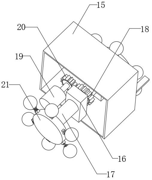
[0029] like Figure 1-7 As shown, on the basis of Embodiment 1, the present invention provides a technical solution: one side of the box body 1 is fixedly connected with a support plate 23, the bottom of the support plate 23 is fixedly connected with the organic case 15, and the inside of the case 15 is fixedly connected with a Two rotating brackets 16, the inside of the cabinet 15 are provided with a rotating shaft rod 17, the rotating shaft rod 17 is rotatably connected to the inside of the two rotating brackets 16, the outside of the rotating shaft rod 17 is fixedly sleeved with a driven gear 18, and the inside of the cabinet 15 is fixedly connected There is a second motor 19, the output end of the second motor 19 is fixedly connected with the driving gear 20, the teeth of the driving gear 20 are engaged with the teeth of the driven gear 18, and the two ends of the rotating shaft rod 17 extend to the outside of the cabinet 15 The two ends of the rotating shaft rod 17 are fixe...
Embodiment 3
[0032] like Figure 1-7 As shown, on the basis of Embodiment 1 and Embodiment 2, the present invention provides a technical solution: both sides of the chassis 15 are fixedly connected with baffles 22 .
[0033] In this embodiment, through the baffle plate 22, the ice-breaking ball 2103 can be limited while the ice-breaking ball 2103 rotates, so that the spring 2102 is deformed, and when the ice-breaking ball 2103 is rotated to a certain angle, the ice-breaking ball 2103 is separated from the baffle plate 22, thereby making the spring 2102 deform. 2102 restores the deformation to speed up the speed at which the ice-breaking ball 2103 hits the rail, thereby increasing the ice-breaking effect.
PUM
 Abstract
Description
Claims
Application Information
 - R&D
- Intellectual Property
- Life Sciences
- Materials
- Tech Scout
- Unparalleled Data Quality
- Higher Quality Content
- 60% Fewer Hallucinations
Browse by: Latest US Patents, China's latest patents, Technical Efficacy Thesaurus, Application Domain, Technology Topic, Popular Technical Reports.
© 2025 PatSnap. All rights reserved.Legal|Privacy policy|Modern Slavery Act Transparency Statement|Sitemap|About US| Contact US: help@patsnap.com


