A top-type prestressed reinforcement machine used in the field of building structure repair and reinforcement
A building structure and prestressing technology, which is applied in building maintenance, building structure, construction, etc., can solve the problems of low material strength utilization rate, limited rigidity improvement, limited improvement effect of structural component bearing capacity and deformation effect, etc.
- Summary
- Abstract
- Description
- Claims
- Application Information
AI Technical Summary
Problems solved by technology
Method used
Image
Examples
Embodiment 1
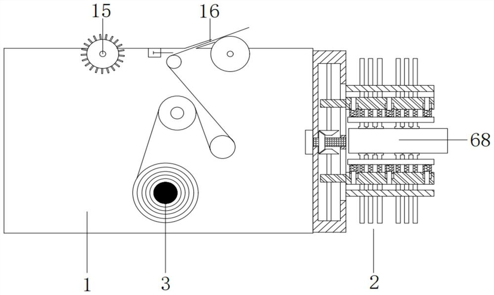
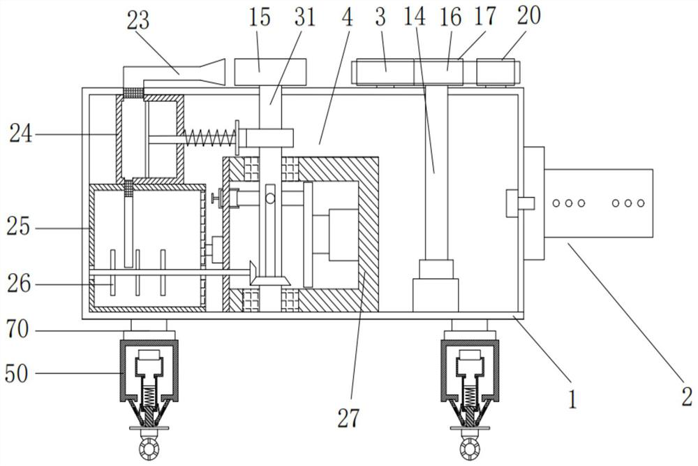
[0040] The embodiment of the present invention provides a top-type prestressing reinforcement machine used in the field of building structure repair and reinforcement, such as Figure 1-Figure 3 As shown, it includes a casing 1, the left side of the casing 1 is fixedly connected with a repairing device 2, the lower end of the casing 1 is provided with four lifting blocks 70, and the right end of the casing 1 is rotated with a rubber coating wheel 15. , the top of the housing 1 is fixedly provided with a feeding mechanism 3, and the feeding mechanism 3 is connected with a tensioning wheel 21, and the tensioning wheel 21 and the gluing wheel 15 are in the same horizontal plane.
[0041] The working principle of the above technical solution is as follows:
[0042] First use the repairing device 2 to repair the surface of the repaired member 68 and smooth it, then apply carbon fiber special glue, apply prestress to the carbon fiber cloth 16 for reinforcement, and then paste the ca...
Embodiment 2
[0046] On the basis of the above Example 1, as Figure 5-Figure 6 As shown, the repairing device 2 includes an installation shell 5 and two repair components. The installation shell 5 is provided with a first cavity 501 inside. The chute 502 is in communication with the first cavity 501, and the two repair components are respectively slidably connected to the chute 502;
[0047] A motor one 601 is fixedly connected to the outer side of the left end of the installation shell 5, and a rotating shaft one 6 is fixedly connected to the motor one 601. The rotating shaft one 6 penetrates the first cavity 501 and is rotatably connected to the mounting shell 5, A bevel gear 1 602 is fixedly connected to the rotating shaft 1 6 , a bevel gear 2 603 is symmetrically meshed on the front and rear sides of the bevel gear 1 602 , and a threaded rod 604 is fixedly connected to the bevel gear 2 603 , and the threaded rod 604 The threaded rod 604 is threadedly connected with the lifting plate 1...
Embodiment 3
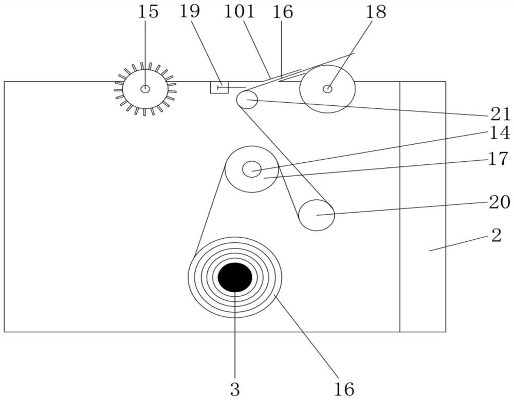
[0055] On the basis of Example 2, as Figure 3-Figure 4 As shown, a carbon fiber cloth 16 is provided outside the feeding mechanism 3, and the carbon fiber cloth 16 is sequentially connected with a transmission wheel 17, an auxiliary support wheel 20, a tension wheel 21 and a drum 18, and the transmission wheel 17 is fixedly connected with a motor The conveying shaft 14, the motor conveying shaft 14 is arranged inside the casing 1, the auxiliary supporting wheel 20 and the roller 18 are arranged in rotation at the upper end of the casing 1, and the tensioning wheel 21 is slidably arranged at the upper end of the casing 1. The upper end of the casing 1, the rear side of the upper end of the casing 1 is provided with a discharge port 101, and the left side of the discharge port 101 is fixedly provided with a cutting device 19;
[0056] The tensioning wheel 21 is connected with a third motor 4701 through a conveying shaft. The third motor 4701 is arranged inside the motor housing...
PUM
 Abstract
Description
Claims
Application Information
 - R&D
- Intellectual Property
- Life Sciences
- Materials
- Tech Scout
- Unparalleled Data Quality
- Higher Quality Content
- 60% Fewer Hallucinations
Browse by: Latest US Patents, China's latest patents, Technical Efficacy Thesaurus, Application Domain, Technology Topic, Popular Technical Reports.
© 2025 PatSnap. All rights reserved.Legal|Privacy policy|Modern Slavery Act Transparency Statement|Sitemap|About US| Contact US: help@patsnap.com


