
Wind tunnel test device

A technology of wind tunnel test and test model, which is applied in the field of wind tunnel test, can solve the problems of increasing the force of supporting equipment, affecting the safety of equipment, and large pressure loss of flow pipes, so as to avoid the interference of flow field, increase the authenticity, Versatile effect

Active Publication Date: 2021-06-29
LOW SPEED AERODYNAMIC INST OF CHINESE AERODYNAMIC RES & DEV CENT
View PDF21 Cites 2 Cited by
  • Summary
  • Abstract
  • Description
  • Claims
  • Application Information

AI Technical Summary

Problems solved by technology

[0006] 1. The angle adjustment mechanism in the prior art is difficult to meet the limit side slip angle or attitude angle requirements of the large side slip angle under the extreme side wind state;
[0007] 2. In the existing technology, under the condition of large sideslip, the flow pipe of the inner flow of the air inlet is seriously bent, which increases the force on the supporting equipment and further affects the safety of the equipment;
[0008] 3. At the same time, when the flow pipe is seriously bent, the pressure loss in the flow pipe will be too large, so that the flow of the flow pipe cannot meet the large flow demand of the nacelle inlet

Method used


Image

  • Wind tunnel test device

Examples


Embodiment 1

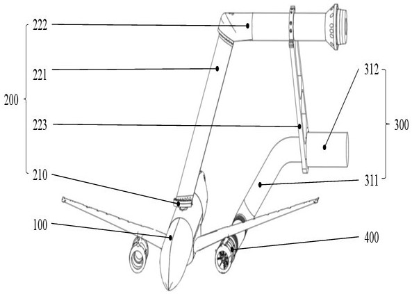
[0037] Such as figure 1 As shown, embodiment 1 of the present invention provides a kind of wind tunnel test device, comprises support system, test model and piping system:

[0038] One end of the support system 200 is connected to the top of the test model 100;

[0039] The test model 100 is provided with a ventilation module 400;

[0040] The pipeline system 300 is connected to the support system 200, and the pipeline system 300 is connected to the test model 100; the pipeline system 300 includes a first pipeline part 311 and a second pipeline part 312, the first pipeline part 311 One end of a pipe part 311 is connected to one end of the ventilation module 400 , and both the first pipe part 311 and the second pipe part 312 are connected to the support system 200 .

[0041] The ventilation module 400 is usually a part of an aircraft engine, generally called a nacelle. The nacelle (Enginenacelle) generally refers to the nacelle inlet on the engine structure. As an important...

Embodiment 2

[0052] Embodiment 2 of the present invention provides a kind of method of wind tunnel test, and concrete steps are as follows:

[0053] Step 1: Connect the pressure measuring points in the air intake duct of the ventilation module 400 with the pressure guiding pipes in accordance with the programmed sequence, and connect them to the steady-state pressure measuring system, test the pressure measuring system and ensure that it can work normally;

[0054] Step 2: Install the pressure sensor on the dynamic pressure measuring point, and then debug to ensure that the dynamic pressure sensor and the data acquisition system can work normally;

[0055] Step 3: Install the support system 200 above the test model 100 through the transfer mechanism 210;

[0056] Step 4: Connect one end of the first pipeline part 311 of the pipeline system 300 to the ventilation module 400 of the test model 100;

[0057] Step 5: Connect the other end of the first pipeline part 311 of the pipeline system 3...


PUM


Abstract

The invention is suitable for the technical field of wind tunnel tests, and provides a wind tunnel test device, which comprises a support system, a test model and a pipeline system, and one end of the support system is connected above the test model; a ventilation module is arranged on the test model; the pipeline system is connected to the support system, and the pipeline system is connected to the test model; the pipeline system comprises a first pipeline part and a second pipeline part, one end of the first pipeline part is connected with one end of the ventilation module, and the first pipeline part and the second pipeline part are both connected to the support system. The wind tunnel test device has the advantages of being stable in pressure, high in universality, simple and convenient to use and capable of meeting the requirement for the large sideslip angle in a limit crosswind state.

Description

technical field [0001] The invention belongs to the technical field of wind tunnel tests, in particular to a wind tunnel test device. Background technique [0002] During take-off and landing at the airport, the aircraft may encounter lateral crosswinds, which will affect the flow field in the air intake of the aircraft engine nacelle. In particular, the nacelle inlet of the engine with a large bypass ratio has a large inlet capture area, and the separation area caused by the lateral crosswind is wide, resulting in excessive distortion of the engine inlet flow field, and even induces engine surge and parking, resulting in safety hazards. Accidents happen. Therefore, the above problems must be solved in the aircraft development process. Among them, the wind tunnel test is an effective method with high safety and low cost. By simulating the flow field characteristics of the nacelle inlet of the aircraft in the wind tunnel under the state of crosswind near the ground, the Th...

Claims


Application Information

Patent Timeline
Patent Type & Authority Applications(China)
IPC IPC(8): G01M9/02G01M9/04G01M9/08
CPCG01M9/02G01M9/04G01M9/08
Inventor 徐彬彬巫朝君王学吴世华马付健
Owner LOW SPEED AERODYNAMIC INST OF CHINESE AERODYNAMIC RES & DEV CENT
Learn More