
Automobile turbocharger middle shell cooling hole unblocking and blocking testing device and method

A turbocharger and testing device technology, which is applied in the direction of measuring devices, machine/structural component testing, mechanical component testing, etc., can solve the problems of inconvenient testing of the middle shell and high labor intensity, and achieve reliable and stable product quality. The effect of reducing labor intensity and quick and clear results

Active Publication Date: 2021-06-29
KEHUA HLDG
View PDF9 Cites 3 Cited by
  • Summary
  • Abstract
  • Description
  • Claims
  • Application Information

AI Technical Summary

Problems solved by technology

[0006] The technical problem to be solved by the present invention is: to overcome the deficiencies of the prior art, to provide a test device and test method for the blockage of the cooling hole of the middle casing of the automobile turbocharger, and to solve the problems of inconvenient and labor-intensive testing of the middle casing in the past

Method used


Image

  • Automobile turbocharger middle shell cooling hole unblocking and blocking testing device and method
  • Automobile turbocharger middle shell cooling hole unblocking and blocking testing device and method
  • Automobile turbocharger middle shell cooling hole unblocking and blocking testing device and method

Examples


Embodiment 1

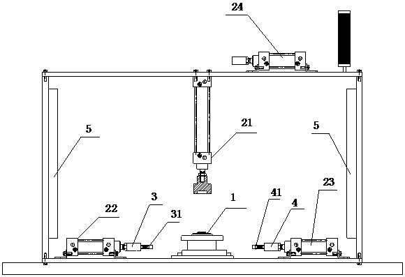
[0018] Such as figure 1 As shown, an automobile turbocharger intermediate shell cooling hole is blocked test device, including a rack, a workpiece clamping cylinder 21, an intake positioning head 3, an air positioning head 4, and a detecting cylinder 24, a rack set up for The mounting station of the mounting intermediate case 1 is fixed to the frame, and the car turbocharger intermediate case 1 is fixed to be detected; at least one intake is provided on the intake positioning head 3. Plug 31, the intake plug 31 is adapted to be connected to the cooling hole of the intermediate case 1, each intake blocker 31 is connected to the intake branch, and the intake branch is provided for controlling the intake branch tube. The air-off refiner 4 is provided on the air positioning head 4, which is adapted to connect to the cooling hole outlet of the intermediate case 1, and the air-proof plug 41 is connected to the air supply. The detecting cylinder 24 is in communication between the airflow...

Embodiment 2

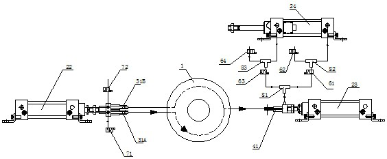
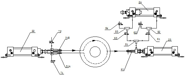
[0028] The intermediate case 1 of the binary and one cooling hole is swolched. Since the second is further out, the intermediate case 1 forms the first cooling inner hole and the second cooling inner hole; the corresponding, intake plug 31 For two, the first intake plug 31a and the second intake blocker 31b are respectively, the number of air-shaped plug 41 is one; the first intake blocker 31a blocks the first intake port, the second intake The plug 31b blocks the second intake port, the venting plug 41 blocks the air outlet; figure 2 As shown, the first cooling inner hole is blocked: the first intake solenoid valve 71, the first detecting solenoid valve 61, the fourth detecting solenoid valve 64 is applied, the second intake solenoid valve 72, the second detection solenoid valve 62. The third detection solenoid valve 63 is absent; the gas entering the first cooling inner hole passes through the air cylinder 24, the first detecting tube, and the second detecting tube enters the de...


PUM


Abstract

The invention relates to an automobile turbocharger middle shell cooling hole unblocking and blocking testing device, which comprises a workpiece clamping air cylinder, an air inlet positioning head, an air outlet positioning head and a detection air cylinder. At least one air inlet plug is arranged on the air inlet positioning head; at least one air outlet plug is arranged on the air outlet positioning head; and the detection air cylinder stretches out or retracts according to the airflow output from an air outlet main pipe so as to identify unblocking and blocking conditions of a cooling channel in a middle shell. According to the testing method, the testing device is adopted, air is inflated into a cooling hole of the middle shell through an air inlet plug, air exhausted from the cooling hole enters the detection air cylinder, and if the detection air cylinder stretches out or retracts within the set time, it is indicated that the cooling hole is smooth; and if the air cylinder is detected not to extend out within the specified time, the cooling hole is blocked. The structure is simple, operation is free and convenient, results are quick and clear, and the labor intensity of operators is greatly reduced.

Description

Technical field [0001] The present invention relates to the field of automotive parts tests, and more particularly to an intermediate case of automotive turbocharger intermediate shell cooling holes to block testing devices and test methods. Background technique [0002] The car turbocharger is mounted on the intake pipe branch of the engine, which makes up for the innate shortcomings of some naturally charged engines, enabling the engine to increase the output power of 10% without changing the working volume of the cylinder. Therefore, this boosting technology is used to improve the output power of the engine, and the high performance of the car is achieved. However, in the case of high temperature, high pressure and high-speed operation, its working environment is very bad, and the work requirements are more demanding, so the technical processing and detection devices are high. One of the "floating bearings" (ie, the middle shell) that support turbine operation is operated. It ...

Claims


Application Information

Patent Timeline
Patent Type & Authority Applications(China)
IPC IPC(8): G01M13/00
CPCG01M13/00
Inventor 赵忠华沙文杰
Owner KEHUA HLDG
Learn More