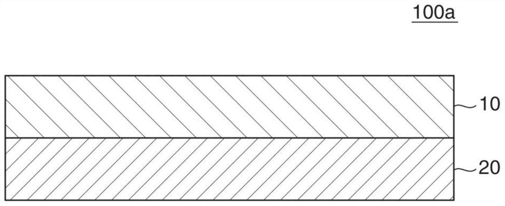
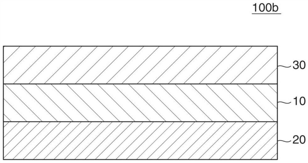
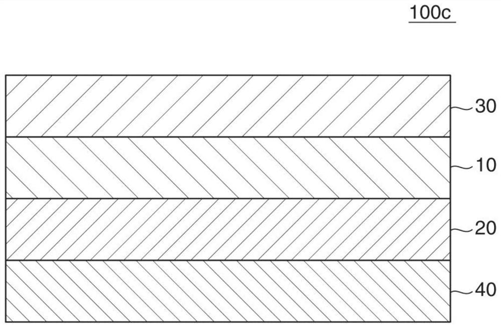
Polarizer protective film, polarizing plate, and image display device
A technology for protective films and polarizers, applied in optical elements, polarizing elements, optics, etc., can solve the problems of uneven color, poor durability, and color difference, and achieve the effect of improving color unevenness and durability.
- Summary
- Abstract
- Description
- Claims
- Application Information
AI Technical Summary
Problems solved by technology
Method used
Image
Examples
Embodiment 1
[0112] 1. Fabrication of polarizer
[0113] A long roll of a polyvinyl alcohol (PVA)-based resin film (manufactured by Kuraray Co., Ltd., product name "PE3000") with a thickness of 30 μm is singled along the longitudinal direction by a roll stretching machine so as to be 5.9 times larger in the longitudinal direction. Swelling, dyeing, crosslinking, and washing treatments were performed simultaneously while axial stretching, and finally drying treatment was performed, thereby producing a polarizer with a thickness of 12 μm.
[0114] Specifically, in the swelling treatment, the film was stretched to 2.2 times while being treated with pure water at 20°C. Next, in the dyeing process, the obtained polarizer was stretched to 1.4° C. while being treated in a 30° C. aqueous solution whose weight ratio of iodine and potassium iodide was adjusted to be 1:7 so that the single transmittance of the obtained polarizer became 45.0%. times. Furthermore, a two-stage cross-linking treatment ...
Embodiment 2
[0123] As the pigment, 0.3 parts by weight of the product name "PD-320" manufactured by Yamamoto Chemical Co., Ltd. was used, and the stretching temperature was set at 139° C. (Tg+9° C.), and coloring was obtained in the same manner as in Example 1. Polarizer protective film. The obtained colored polarizer protective film had a thickness of 30 μm, a front retardation Re(550) of 135 nm, and a maximum absorption wavelength at 590 nm. In addition, the slow axis direction is 135° with respect to the longitudinal direction.
[0124] Except for using the above-mentioned colored polarizer protective film, it carried out similarly to Example 1, and obtained the elongated polarizing plate 2 which has the structure of protective film / polarizer / colored polarizer protective film.
[0125] An acrylic adhesive layer was provided on the surface of the polarizing plate 2 on the side of the colored polarizer protective film, and the acrylic adhesive layer was bonded to one side of an organic ...
Embodiment 3
[0127] A colored polarizer protective film was obtained in the same manner as in Example 1 except that the amount of the dye added was 0.18 parts by weight and the stretching temperature was 142° C. (Tg+12° C.). The obtained colored polarizer protective film had a thickness of 20 μm, a front retardation Re(550) of 100 nm, and a maximum absorption wavelength at 590 nm. In addition, the slow axis direction is 135° with respect to the longitudinal direction.
[0128] A strip-shaped polarizing plate 3 having a composition of protective film / polarizer / colored polarizer protective film was obtained in the same manner as in Example 1 except for using the above-mentioned colored polarizer protective film.
[0129] An acrylic adhesive layer was provided on the protective film (TAC film) side surface of the polarizing plate 3 , and laminated to one side of an organic EL panel of 55 inches or more through the acrylic adhesive layer to obtain a laminate 3 .
PUM
| Property | Measurement | Unit |
|---|---|---|
| Thickness | aaaaa | aaaaa |
| Thickness | aaaaa | aaaaa |
| Thickness | aaaaa | aaaaa |
Abstract
Description
Claims
Application Information
 - R&D
- Intellectual Property
- Life Sciences
- Materials
- Tech Scout
- Unparalleled Data Quality
- Higher Quality Content
- 60% Fewer Hallucinations
Browse by: Latest US Patents, China's latest patents, Technical Efficacy Thesaurus, Application Domain, Technology Topic, Popular Technical Reports.
© 2025 PatSnap. All rights reserved.Legal|Privacy policy|Modern Slavery Act Transparency Statement|Sitemap|About US| Contact US: help@patsnap.com


