
Self-adjusting photovoltaic panel

A photovoltaic panel and self-adjusting technology, applied in photovoltaic modules, photovoltaic power generation, photovoltaic module support structures, etc., can solve the problems of increased cost, high cost, poor use effect, etc., and achieve the effect of improving power generation efficiency

Inactive Publication Date: 2021-06-29
湖州瑞讯机电设备有限公司
View PDF0 Cites 6 Cited by
  • Summary
  • Abstract
  • Description
  • Claims
  • Application Information

AI Technical Summary

Problems solved by technology

[0003] However, the existing solar photovoltaic panels are installed in a fixed way, and the inclination angle of the solar photovoltaic panel installation remains unchanged, so the maximum power generation efficiency cannot be achieved, and the use effect is poor. There are also some solar photovoltaic panel installations on the market. There are sun tracking systems, most of which use clock program control and light sensor control. Clock program control is to write clock program timing according to astronomical laws or continuously control the forward and reverse rotation of the drive motor to achieve sun tracking; light sensor control is to use light sensor Detect the change of the sun angle, feed back the signal to the controller, and then the controller controls the forward or reverse rotation of the motor to track the sun. Generally speaking, the sun tracking system controlled by the clock program and the light sensor needs to use an intelligent system based on a single-chip microcomputer or PLC. Control circuit, so the installation cost is high, and because the device is placed outdoors, it needs to be maintained frequently, which increases the cost

Method used


Image

  • Self-adjusting photovoltaic panel
  • Self-adjusting photovoltaic panel
  • Self-adjusting photovoltaic panel

Examples


Embodiment Construction

[0018] The following examples are for illustrative purposes only and are not intended to limit the scope of the invention.

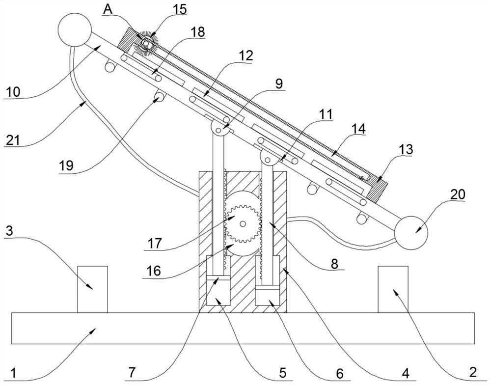
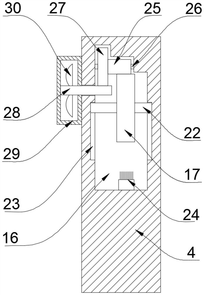
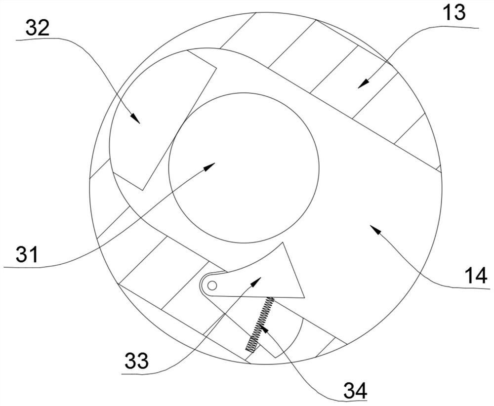
[0019] refer to Figure 1-3 , a self-adjusting photovoltaic panel, comprising a bearing base 1, a first airbag 2 is arranged on the bearing base 1, a second airbag 3 is arranged on the other side of the bearing base 1, a fixing block 4 is welded and fixed at the center of the bearing base 1, and the fixed There is a first cavity 5 inside the block 4, and a second cavity 6 is opened on the other side of the fixed block 4. The first cavity 5 and the second cavity 6 are slidingly connected with a baffle 7 inside, and the top of the baffle 7 A rack 8 is welded and fixed, and the rack 8 runs through the fixed block 4. One end of the rack 8 located outside the fixed block 4 is connected to a movable seat 9 through a pin shaft, and the movable seat 9 is connected to a support plate 10, and the top of the support plate 10 is set There are several photovoltaic p...


PUM


Abstract

The invention discloses a self-adjusting photovoltaic panel which comprises a bearing base. A first air bag is arranged on the bearing base, a second air bag is arranged on the other side of the bearing base, a fixing block is welded and fixed to the center position of the bearing base, a first cavity is formed in the fixing block, a second cavity is formed in the other side of the fixing block, baffles are slidably connected to the interiors of the first cavity and the second cavity, racks are welded and fixed to the upper portions of the baffles, the racks penetrate through the fixing blocks, movable seats are rotatably connected to the ends, located outside the fixing blocks, of the racks through pin shafts, the movable seats are jointly connected with a supporting plate, and a plurality of photovoltaic panels are arranged at the top of the supporting plate. The photovoltaic panel has the advantages that by utilizing the principle that a gas expands after being heated, due to the fact that the two ends are irradiated by the sun differently, the sizes are different, the supporting plate inclines, the photovoltaic panel can receive more sunlight, and the power generation efficiency is improved.

Description

technical field [0001] The invention relates to the technical field of photovoltaic panels, in particular to a self-regulating photovoltaic panel. Background technique [0002] Photovoltaic power generation is a technology that directly converts light energy into electrical energy by using the photovoltaic effect at the semiconductor interface. It is mainly composed of three parts: solar panels (components), controllers and inverters, and the main components are composed of electronic components. The solar cells are packaged and protected after being connected in series to form a large-area solar cell module, and then cooperate with power controllers and other components to form a photovoltaic power generation device. [0003] However, the existing solar photovoltaic panels are installed in a fixed way, and the inclination angle of the solar photovoltaic panel installation remains unchanged, so the maximum power generation efficiency cannot be achieved, and the use effect i...

Claims


Application Information

Patent Timeline
Patent Type & Authority Applications(China)
IPC IPC(8): H02S20/30H02S40/10F24S30/425F24S30/00
CPCF24S30/425F24S2030/11F24S2030/134H02S20/30H02S40/10Y02E10/47Y02E10/50
Inventor 赵月红
Owner 湖州瑞讯机电设备有限公司
Learn More