Plastic recycling and water washing treatment equipment

A technology for washing treatment and plastic recycling, applied in plastic recycling, mechanical material recycling, recycling technology, etc., can solve problems such as large water consumption and water resource waste, and achieve the effect of saving washing water and reliable operation environment.

Pending Publication Date: 2021-07-02
李强
View PDF0 Cites 0 Cited by
  • Summary
  • Abstract
  • Description
  • Claims
  • Application Information

AI Technical Summary

Problems solved by technology

[0002] In the process of plastic recycling, the plastic needs to be crushed and cleaned. The traditional treatment method consumes too much water and is easy to cause waste of water resources. Therefore, a plastic recycling washing treatment equipment is designed.

Method used


Image

  • Plastic recycling and water washing treatment equipment
  • Plastic recycling and water washing treatment equipment
  • Plastic recycling and water washing treatment equipment

Examples


specific Embodiment approach 1

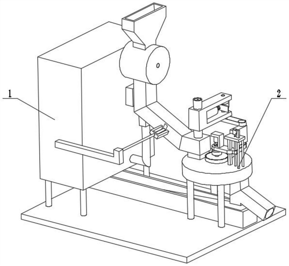
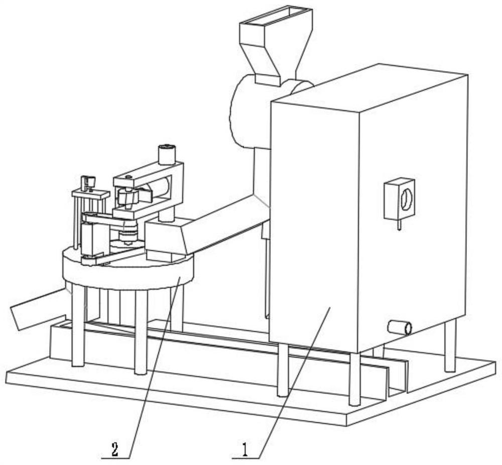
[0029] Combine below figure 1 , figure 2 , image 3 , Figure 4 , Figure 5 , Figure 6 , Figure 7 , Figure 8 , Figure 9 , Figure 10 , Figure 11 , Figure 12 , Figure 13 , Figure 14 Describe this embodiment, the present invention relates to a kind of plastic recycling equipment, more specifically a kind of plastic recycling water washing treatment equipment, including air flow management anti-blocking mechanism 1, crushing mechanism 2, the equipment can be crushed, and the equipment can activate the crushed The equipment can ensure a more reliable operating environment, and the equipment can save water for washing.

[0030] The air flow control and anti-blocking mechanism 1 is connected with the crushing mechanism 2 .

specific Embodiment approach 2

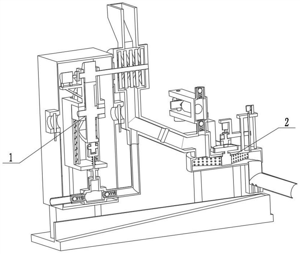
[0032] Combine below figure 1 , figure 2 , image 3 , Figure 4 , Figure 5 , Figure 6 , Figure 7 , Figure 8 , Figure 9 , Figure 10 , Figure 11 , Figure 12 , Figure 13 , Figure 14 Describe this embodiment, this embodiment will further explain Embodiment 1, the air flow control and anti-blocking mechanism 1 includes a gate with a rod 1-1, a positive pressure pipe nozzle 1-2, a box body 1-3, and a connecting seat 1 -4. Outrigger 1-5, air outlet 1-6, crushing wheel 1-7, crushing shaft 1-8, inlet 1-9, air inlet pipe 1-10, cam 1-11, coupling 1- 12. Motor 1-13, fixed frame 1-14, belt shaft wheel 1-15, filter plate 1-16, movable bearing seat 1-17, chute 1-18, limit column 1-19, spring 1-20 , blade 1-21, belt pulley seat 1-22, return spring 1-23, inlet 1-24, intake check valve 1-25, transfer gas box 1-26, inner piston 1-27, outlet check valve Valve 1-28, seat post with limiter 1-29, positive pressure tube 1-30, filter plate I1-31, hinged arm 1-32, connecting se...

specific Embodiment approach 3

[0034] Combine below figure 1 , figure 2 , image 3 , Figure 4 , Figure 5 , Figure 6 , Figure 7 , Figure 8 , Figure 9 , Figure 10 , Figure 11 , Figure 12 , Figure 13 , Figure 14Describe this embodiment, this embodiment will further explain Embodiment 1. The crushing mechanism 2 includes a base 2-1, a water tank 2-2, a leg I2-3, a washing tank 2-4, and a delivery pipeline 2- 5. Hole seat 2-6, gate matching slideway 2-7, water outlet seat 2-8, crushing box 2-9, crushing entry bucket 2-10, water inlet check valve 2-11, water inlet pipe 2-12 , water body transfer box 2-13, piston tube 2-14, piston rod 2-15, spring I2-16, matching seat 2-17, belt shaft cam 2-18, pulley I2-19, belt 2-20, belt shaft Belt pulley I2-21, servo motor 2-22, secondary platform 2-23, lead screw 2-24, belt pulley III2-25, movable platform 2-26, limit column I2-27, secondary support leg 2-28, Washing motor 2-29, coupling I2-30, driving disc with protrusion 2-31, driven disc with shaf...


PUM


Abstract

The invention relates to plastic recycling equipment, in particular to plastic recycling and water washing treatment equipment. The plastic recycling and water washing treatment equipment comprises an airflow treatment anti-blocking mechanism and a crushing mechanism. The equipment can conduct crushing, can activate crushed materials, can guarantee a reliable operation environment and can save water for water washing. The airflow treatment anti-blocking mechanism is connected with the crushing mechanism.

Description

technical field [0001] The invention relates to a plastic recycling equipment, more specifically a plastic recycling washing treatment equipment. Background technique [0002] In the process of plastic recycling, the plastic needs to be crushed and cleaned. The traditional treatment method consumes too much water, which is easy to cause waste of water resources. Therefore, a plastic recycling washing treatment equipment is designed. Contents of the invention [0003] The technical problem mainly solved by the present invention is to provide a washing treatment equipment for plastic recycling, which can be crushed, can activate the crushed material, can ensure a relatively reliable operating environment, and can save washing water. [0004] In order to solve the above technical problems, the present invention relates to a plastic recycling equipment, more specifically, a plastic recycling washing treatment equipment, including an air flow control and anti-blocking mechanism...

Claims


Application Information

Patent Timeline
Patent Type & Authority Applications(China)
IPC IPC(8): B29B17/04B29B17/00
CPCB29B17/00B29B17/0412B29B2017/0015B29B2017/044Y02W30/52Y02W30/62
Inventor 李强
Owner 李强
Why Eureka
Try Eureka