Reed particle combustion transverse fire grate

A technology of horizontal placement and grate, which is applied in the direction of combustion method, combustion equipment, grate, etc., can solve the problems of black smoke from reed particles, low burnout rate, and influence on combustion, so as to change the uneven air distribution and avoid The effect of polluting the environment

Pending Publication Date: 2021-07-02
孙路军
View PDF0 Cites 2 Cited by
  • Summary
  • Abstract
  • Description
  • Claims
  • Application Information

AI Technical Summary

Problems solved by technology

It is mainly to solve the combustion of terrestrial plant particles and the combustion of biomass particles containing alkali metals and high silicon content. There is no effective grate
Especially the lignin in the process of burning aquatic plant reed pellets increases viscosity, bridges and accumulates in the form of a grid after burning, which makes it difficult to burn reed pellets
[0003] However, the combustion of reed particles has always had black smoke at the initial stage of ignition and at the time of flameout, coking at the later stage of combustion, and severe fly ash of volatile matter in the pre-combustion stage. There has been no breakthrough for many years.
Among them, the air distribution is uneven, which affects the combustion. The biomass particles jump up and down between the grates, which is not easy to ignite. During the fire-off stage, due to the large air distribution, the slag leaks down, the burnout rate is not high, and the ash slag increases, which wastes energy.
When the air distribution is small, heap combustion is formed. Due to insufficient air distribution, volatile combustion is mixed with particulate matter and unburned carbon particles in the form of flue gas, which are freely discharged into the atmosphere and increase pollutant emissions. The formed negative pressure moves to the rear of the furnace for combustion, causing the furnace to hang on the wall and the grate to coke

Method used


Image

  • Reed particle combustion transverse fire grate
  • Reed particle combustion transverse fire grate

Examples


Embodiment Construction

[0015] The following will clearly and completely describe the technical solutions in the embodiments of the present invention with reference to the accompanying drawings in the embodiments of the present invention. Obviously, the described embodiments are only some, not all, embodiments of the present invention. Based on the embodiments of the present invention, all other embodiments obtained by persons of ordinary skill in the art without making creative efforts belong to the protection scope of the present invention.

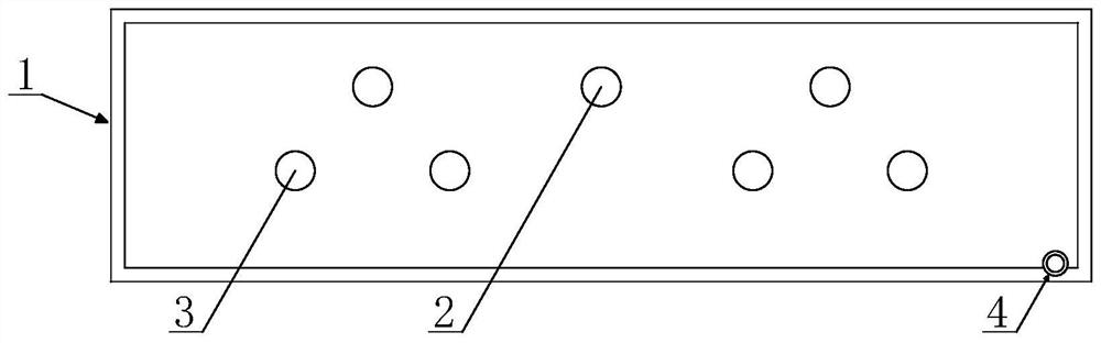
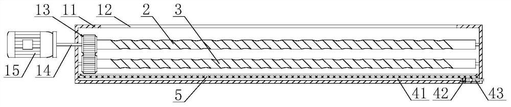
[0016] see Figure 1-2 , a reed particle burning horizontal fire grate, comprising a horizontal fire grate assembly 1, a drive shaft fire bar 2, a driven shaft fire bar 3 and an ash discharge port 4, the drive shaft fire bar 2 is arranged inside the horizontal fire grate assembly 1, Below the driving shaft grate 2, there is a driven shaft grate 3. The driving shaft grate 2 and the driven shaft grate 3 can be increased or decreased according to the demand. The...


PUM


Abstract

The invention discloses a reed particle combustion transverse fire grate. The reed particle combustion transverse fire grate comprises a transverse fire grate assembly, a driving shaft fire bar, a driven shaft fire bar, an ash discharging opening and a dust falling net. According to the reed particle combustion transverse fire grate, combusted reed particles enter an external frame body through a bell and spigot type ash groove, a driving motor is started, the driving motor drives an internal linkage gear to rotate reversely through a connecting rod, the internal linkage gear and a driving shaft gear are meshed with each other, the internal linkage gear drives the driving shaft gear to rotate in the forward direction, the driving shaft gear and a driven shaft gear are meshed with each other, the driving shaft gear drives the driven shaft gear to rotate in the reverse direction, and ash is discharged into an ash collecting groove through the dust falling net and then discharged to the outside in a centralized mode through an external ash discharging pipe. Through the structure, the ash sinks, and the ash is collected, so that environment pollution is avoided.

Description

technical field [0001] The invention relates to the technical field of fire grate, in particular to a horizontal fire grate for burning reed particles. Background technique [0002] The grate is used as a component for stacking solid fuels in boilers or industrial furnaces and making them burn effectively. Among them, the biomass particle burning grate is mostly set in the forward direction, which is divided into three types: push type grate, rolling type grate, and lifting type grate. category. The main purpose is to solve the burning of terrestrial plant particles and the combustion of biomass particles containing alkali metals and high silicon content. There is no effective grate yet. In particular, lignin in the process of burning aquatic plant reed pellets increases viscosity, bridges and accumulates in the form of a grid after burnout, which makes it difficult to burn reed pellets. [0003] However, the combustion of reed particles has always had black smoke at the i...

Claims


Application Information

Patent Timeline
Patent Type & Authority Applications(China)
IPC IPC(8): F23H9/08F23J1/00
CPCF23H9/08F23J1/00
Inventor 孙路军徐建中孙涛谢吉星范鹏飞许鹏飞马腾
Owner 孙路军
Why Eureka
Try Eureka