Frequency detection circuit and method for quickly calculating electrical parameters of motor
A frequency detection circuit and fast calculation technology, applied in the field of motors, can solve problems such as rapid testing of unfavorable motors, long waiting time, damaged motors, etc., and achieve the effects of abundant samples, shortened time, and accurate conclusions.
- Summary
- Abstract
- Description
- Claims
- Application Information
AI Technical Summary
Problems solved by technology
Method used
Image
Examples
Embodiment 1
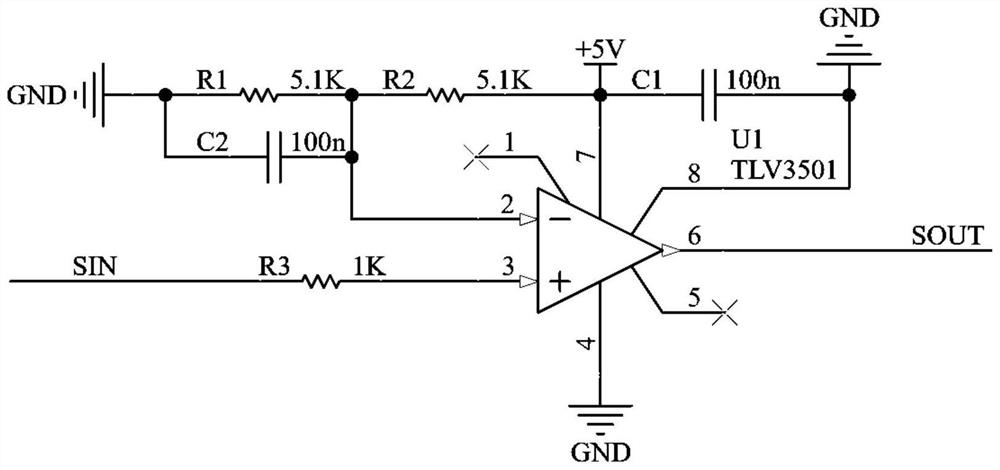
[0044] Such as figure 1 As shown, a frequency detection circuit includes a resistor R1, a resistor R2, a resistor R3, a capacitor C1, a capacitor C2 and a comparator U1. In this example, the comparator U1 uses a TLV3501 integrated chip. Pin 7 of the comparator U1 is connected to a 5V power supply, and pin 4 of the comparator U1 is grounded. Pin 3 of the comparator U1 is connected to the resistor R3, and the other end of the resistor R3 is connected to the output signal of the motor. The second pin of the comparator U1 is respectively connected to one end of the resistor R1, the resistor R2 and the capacitor C2, the other end of the capacitor C2 and the resistor R1 is grounded, and the other end of the resistor R2 is connected to a 5V power supply. The 8-pin of the comparator U1 is grounded, and the 8-pin is also connected to one end of the capacitor C1, and the other end of the capacitor C1 is connected to a 5V power supply. Among them, the 1 pin and the 5 pin of the compara...
PUM
 Abstract
Description
Claims
Application Information
 - R&D
- Intellectual Property
- Life Sciences
- Materials
- Tech Scout
- Unparalleled Data Quality
- Higher Quality Content
- 60% Fewer Hallucinations
Browse by: Latest US Patents, China's latest patents, Technical Efficacy Thesaurus, Application Domain, Technology Topic, Popular Technical Reports.
© 2025 PatSnap. All rights reserved.Legal|Privacy policy|Modern Slavery Act Transparency Statement|Sitemap|About US| Contact US: help@patsnap.com


