Sealing structure of miniature blood pump, handle head assembly of miniature blood pump and miniature blood pump
A sealing structure and sealing technology, applied in the directions of blood pumps, blood pumps, hypodermic injection devices, etc., can solve problems such as affecting the normal operation of the micro blood pump, poor sealing effect of the micro blood pump, and easy liquid flow into the motor side.
- Summary
- Abstract
- Description
- Claims
- Application Information
AI Technical Summary
Problems solved by technology
Method used
Image

Examples
Embodiment 1
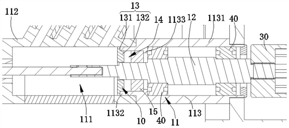
[0036] Please refer to figure 1 . This embodiment provides a sealing structure 10 of a micro-blood pump, which includes a housing 11, a rotating shaft 12 and a sealing cover 13. The housing 11 has a return cavity 111 inside, and the return cavity 111 is used for the flow of liquid. The rotating shaft 12 is at least partially inserted in the return cavity 111 . The sealing cover 13 is installed on the housing 11 and sleeved on the rotating shaft 12 correspondingly, and the sealing cover 13 is located on the part of the rotating shaft 12 inserted into the return cavity 111 . A side of the sealing cover 13 away from the return cavity 111 together with the casing 11 and the rotating shaft 12 forms a sealing cavity 14, and the sealing cavity 14 is filled with a sealing material. Therefore, the liquid in the backflow chamber 111 can be blocked by the sealing material in the sealing chamber 14, so that the liquid in the backflow chamber 111 cannot pass through the sealing material,...
Embodiment 2
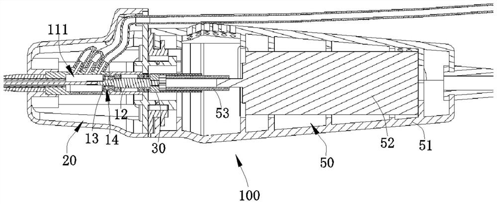
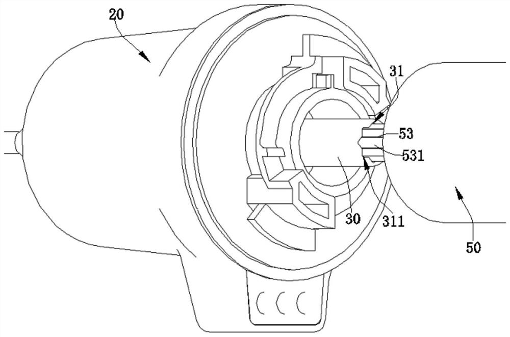
[0043] Please refer to figure 2 . This embodiment provides a handle head assembly 20 of a micro blood pump, which includes the sealing structure 10 of the micro blood pump in Embodiment 1 and a first connector 30, and the first connector 30 is used to connect with the The handle head assembly 20 of the micro blood pump is connected to the driving mechanism in the handle of the micro blood pump used in conjunction with the micro blood pump. The first connector 30 is installed on the end of the rotating shaft 12 away from the return chamber 111, and the first connector 30 A connecting head 30 can drive the rotating shaft 12 to rotate.
[0044] Preferably, the handle head assembly 20 of the micro blood pump further includes a bearing 40, the bearing 40 is arranged between the rotating shaft 12 and the housing 11, so that the rotating shaft can be well aligned by the bearing 40 12 is supported to ensure that the rotating shaft 12 can run stably. Specifically, the bearing 40 is...
Embodiment 3
[0046] Please refer to figure 2 with image 3 . This embodiment provides a micro blood pump 100, which includes the handle head assembly 20 of the micro blood pump in the second embodiment and the handle assembly 50 detachably connected with the handle head assembly 20 of the micro blood pump. The handle assembly 50 includes a handle housing 51, a driving mechanism 52 disposed in the handle housing 51, and a second connector 53 disposed on the output shaft of the driving mechanism 52, the second connector 53 corresponding to the first A connecting head 30 is provided and can drive the first connecting head 30 to rotate. Specifically, the driving mechanism 52 is a motor. That is, in this embodiment, the micro blood pump 100 has an external motor structure. Since the handle assembly 50 is detachable, the driving mechanism 52 can be reused, which is beneficial to reduce costs. And the structure of the external motor can also have a larger torque. It can be understood that,...
PUM
 Abstract
Description
Claims
Application Information
 - R&D
- Intellectual Property
- Life Sciences
- Materials
- Tech Scout
- Unparalleled Data Quality
- Higher Quality Content
- 60% Fewer Hallucinations
Browse by: Latest US Patents, China's latest patents, Technical Efficacy Thesaurus, Application Domain, Technology Topic, Popular Technical Reports.
© 2025 PatSnap. All rights reserved.Legal|Privacy policy|Modern Slavery Act Transparency Statement|Sitemap|About US| Contact US: help@patsnap.com