Surface rust removal treatment process for electrophoresis machining

A treatment process and electrophoresis technology, applied in the field of surface rust removal treatment technology for electrophoresis processing, can solve the problems of low rust removal work efficiency, obstruction of electrophoresis paint, and inability to carry out large batches.

Active Publication Date: 2021-07-06
佛山市顺德区锦上花涂装工艺有限公司
View PDF9 Cites 1 Cited by
  • Summary
  • Abstract
  • Description
  • Claims
  • Application Information

AI Technical Summary

Problems solved by technology

[0002] With the development of technological level, electrophoretic coating technology has gradually replaced traditional spraying technology and has been widely used in industrial production; to carry out electrophoretic coating, the surface of the product must be derusted; at this stage, for electrophoretic coating There are few special derusting devices. Manual derusting methods are used. The work intensity of workers is high, the working environment is harsh, and the efficiency of derusting is low. The use of acid solution for derusting is costly and improper treatment of acid solution will pollute the environment. ; Therefore, the current factory has achieved the purpose of rust removal through ultrasonic cleaning before electrophoresis. Ultrasonic rust removal is mainly done by using the synergistic effect of chemical agents and ultrasonic waves on the "cavitation" of the workpiece; the work The personnel first put all the workpieces into the ultrasonic cleaning tank and then clean them. However, due to the lack of existing technology, the rust on the contact part between the workpieces cannot be cleaned by ultrasonic waves, so that the rust removal on the surface of the workpiece after cleaning is not complete. The rust will hinder the electrophoretic paint, which will affect the electrophoretic effect of the workpiece
[0003] For example, a Chinese patent with application number CN201820658147.3 discloses a rust removal devi...

Method used


Image

  • Surface rust removal treatment process for electrophoresis machining
  • Surface rust removal treatment process for electrophoresis machining
  • Surface rust removal treatment process for electrophoresis machining

Examples


Embodiment approach

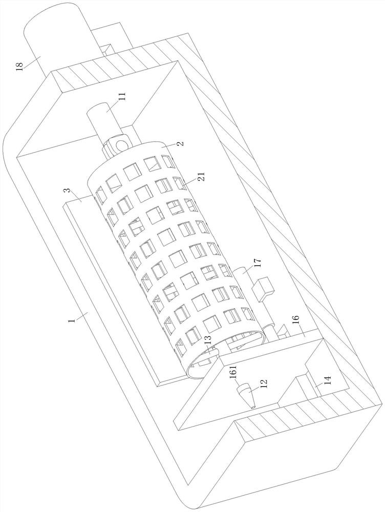
[0044]As an embodiment of the present invention, the rotation direction of the motor 18 driving the discharge cylinder 2 is the same as the direction in which the other end of the shrapnel 22 is facing one end under pressure; Rotation direction, so that the workpiece between one of the shrapnel 22 and the inner wall of the discharge cylinder 2 can move to the adjacent shrapnel 22 under the action of gravity, thereby applying pressure to the shrapnel 22, ensuring that the present invention can be implemented. The direction of rotation of the motor 18 driving the discharge barrel 2 is opposite to the direction in which the other end of the shrapnel 22 faces one end under pressure, which will cause the workpiece to be stuck between the shrapnel 22 and the inner wall of the discharge barrel 2, causing the shrapnel 22 to fail to lift the workpiece. To the buffering effect, and then affect the implementation effect of the present invention.

[0045] As an embodiment of the present i...


PUM


Abstract

The invention relates to the technical field of surface rust removal treatment, in particular to a surface rust removal treatment process for electrophoresis machining. A rust removal device used in the process comprises a rectangular pool, a discharging barrel, an ultrasonic generator and a controller; one side wall of the rectangular pool is rotationally connected with a rotating rod; one end of the rotating rod is hinged to a rotating shaft; the discharging barrel is arranged on the rotating shaft in a sleeving manner; the rotating shaft is located at the center axis of the discharging barrel and fixedly connected with the inner wall of the discharging barrel through a supporting rod; and an opening is formed in the end, away from the rotating rod, of the discharging barrel. According to the rust removal device used in the surface rust removal treatment process for electrophoresis machining, a workpiece is driven by the discharging barrel to rotate in the rectangular pool, and then ultrasonic waves emitted by an ultrasonic wave emitter are used in cooperation, so that the workpiece in the discharging barrel is subjected to rust removal while shaking, the purpose of dead-corner-free rust removal of the workpiece is achieved, the cleanliness of the surface of the workpiece is improved, and the electrophoresis effect of the workpiece is promoted.

Description

technical field [0001] The invention relates to the technical field of surface derusting treatment, in particular to a surface derusting treatment process for electrophoresis processing. Background technique [0002] With the development of technological level, electrophoretic coating technology has gradually replaced traditional spraying technology and has been widely used in industrial production; to carry out electrophoretic coating, the surface of the product must be derusted; at this stage, for electrophoretic coating There are few special derusting devices. Manual derusting methods are used. The work intensity of workers is high, the working environment is harsh, and the efficiency of derusting is low. The use of acid solution for derusting is costly and improper treatment of acid solution will pollute the environment. ; Therefore, the current factory has achieved the purpose of rust removal through ultrasonic cleaning before electrophoresis. Ultrasonic rust removal is...

Claims


Application Information

Patent Timeline
IPC IPC(8): B08B3/12B08B13/00
CPCB08B3/12B08B13/00
Inventor 金越洲
Owner 佛山市顺德区锦上花涂装工艺有限公司
Why Eureka
Try Eureka