A frame for driverless wire-controlled chassis

An unmanned, wire-controlled technology, applied to vehicle components, substructure, transportation and packaging, etc., can solve the problems of reduced ability to withstand alternating loads, large local stress at the plate weld, limited length of the fixed screw, etc. , to achieve the effect of improving the ability to withstand alternating loads, improving the overall reliability, and increasing the length of force

Active Publication Date: 2022-07-19
上海济驭科技有限公司
View PDF10 Cites 0 Cited by
  • Summary
  • Abstract
  • Description
  • Claims
  • Application Information

AI Technical Summary

Problems solved by technology

The mainstream brake-by-wire system mounting bracket is cut and welded by flat steel plates. The brake-by-wire system is fixed on a flat plate through screws, and the flat plate is welded to the frame rod system. The stress is large, and at the same time, due to the limited thickness of the plate, the force length of the fixed screw is limited, which reduces the ability of the screw to withstand alternating loads after being tightened
[0003] At present, the installation method of the front and rear suspensions is mainly by welding the suspension connecting rod lugs on the frame rod system. Since the connection points of the suspension and the frame are subjected to large alternating loads for a long time, its influence on the connecting rod lugs Welding reliability puts forward higher requirements. Due to the thermal stress in welding, the connection strength of welding parts will be low. In order to improve the reliability of the frame and ensure the safety performance of the vehicle, it is necessary to optimize the connection method of the suspension link and the frame.

Method used


Image

  • A frame for driverless wire-controlled chassis
  • A frame for driverless wire-controlled chassis
  • A frame for driverless wire-controlled chassis

Examples


Embodiment Construction

[0021] The technical solutions in the embodiments of the present invention will be clearly and completely described below with reference to the accompanying drawings in the embodiments of the present invention. Obviously, the described embodiments are only a part of the embodiments of the present invention, but not all of the embodiments.

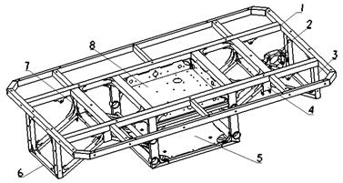
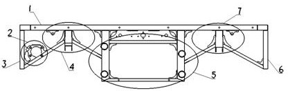
[0022] like Figure 1-5 As shown, a frame for an unmanned drive-by-wire chassis includes a carriage mounting surface 1, a wire-controlled brake system mounting bracket 2, a rear anti-collision buffer mechanism mounting surface 3, and a front anti-collision buffer mechanism mounting surface 6. Suspension mounting bracket group 4 and front suspension mounting bracket group 7, battery mounting box 5, electrical device mounting box 8.

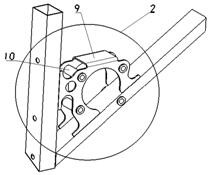
[0023] Preferably, the brake-by-wire system mounting bracket 2 is composed of a connection block 9 and a bolt-fixed bushing 10 ; the number of the connection block 9 includes but is not limited to one piece, and...


PUM


Abstract

The invention belongs to the technical field of unmanned wire-controlled chassis, and discloses a vehicle frame for an unmanned wire-controlled chassis, comprising a carriage mounting surface (1), a wire-controlled brake system mounting bracket (2), a rear anti-collision buffer Mechanism mounting surface (3) and front anti-collision buffer mechanism mounting surface (6), rear suspension mounting bracket group (4) and front suspension mounting bracket group (7), battery mounting box (5), and electrical device mounting box (8). The invention optimizes the structure of the unmanned wire-controlled chassis frame and improves the overall reliability of the frame. The brake-by-wire system mounting bracket (2) is mainly made of sheet metal cutting and bending, and is welded on the frame rod to form a three-dimensional force-bearing structure. The ability to alternate loads, thereby improving the installation reliability of the brake-by-wire system.

Description

technical field [0001] The invention belongs to the technical field of unmanned wire-controlled chassis, and in particular relates to a vehicle frame for an unmanned wire-controlled chassis. Background technique [0002] At present, the production and processing of the frame of the small unmanned drive-by-wire chassis is still in the stage of small batches, and most of the frames are cut and welded from standard profiles. The structural design of the frame and the welding process play a crucial role in the reliability and durability of the frame. The mainstream brake-by-wire system mounting bracket is cut and welded from a flat steel plate. The brake-by-wire system is fixed on a flat plate through a screw, and the flat plate is welded on the frame rod system. The stress is large, and at the same time, due to the limited thickness of the plate, the force length of the fixed screw is limited, which reduces the ability of the screw to withstand alternating loads after being ti...

Claims


Application Information

Patent Timeline
Patent Type & Authority Patents(China)
IPC IPC(8): B62D21/09B62D21/11B62D21/15
CPCB62D21/09B62D21/11B62D21/15
Inventor 罗永昌池晓明吴继翔孙同强罗宁波
Owner 上海济驭科技有限公司
Why Eureka
Try Eureka