Portable optical fiber patch cord coiling device

A fiber optic jumper, portable technology, applied in the field of portable fiber optic jumper coiling device, can solve the problems of clutter, confusion, jumper loose turns and other problems in the equipment room

Pending Publication Date: 2021-07-06
国网河南省电力公司社旗县供电公司
View PDF10 Cites 0 Cited by
  • Summary
  • Abstract
  • Description
  • Claims
  • Application Information

AI Technical Summary

Problems solved by technology

Nowadays, with the development of smart grid, all kinds of power equipment need to realize remote control and data collection and transmission through optical fiber communication. As jumpers connecting equipment to optical fiber wiring links, problems encountered in laying them are also increasing. Outstanding, firstly, the existing optical fiber jumpers are reels with a uniform length. In the actual use process, there are often many remaining problems, and the redundant jumpers cause the equipment room to be messy and not clean enough. Beautiful; second, because the fiber optic jumper wire body is soft and thin, the jumper wires on the whole plate are scattered and chaotic, and the layout is inconvenient, which affects the layout efficiency

Method used


Image

  • Portable optical fiber patch cord coiling device
  • Portable optical fiber patch cord coiling device
  • Portable optical fiber patch cord coiling device

Examples


Embodiment 1

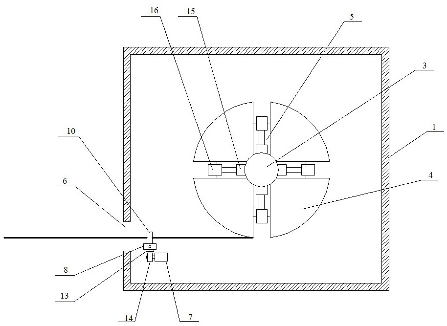
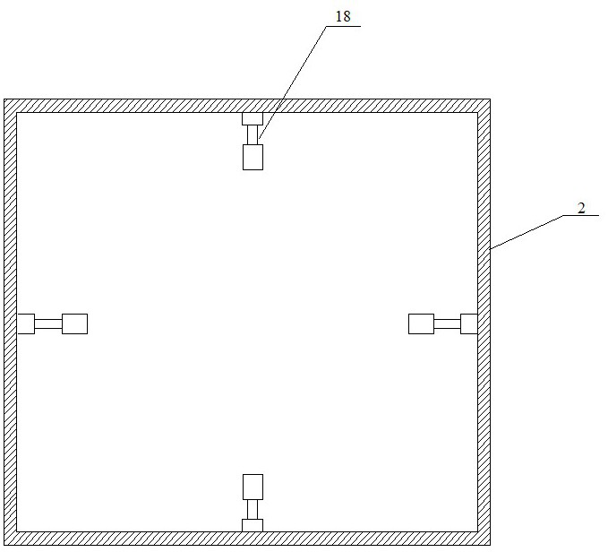
[0029] Such as Figure 1~3As shown, a portable optical fiber jumper coiling device includes a box body 1 hinged on one side and a box cover 2, and a coiling assembly for coiling an optical fiber jumper is arranged in the box body 1, and is used to coil the optical fiber A regular guide assembly for the jumper, and a first fixing component for fixing the inner side of the coiled optical fiber jumper; the inner side of the cover 2 is provided with a second fixing unit for fixing the outer side of the coiled optical fiber jumper Fixed assembly; the coiling assembly includes a driving motor, a rotating shaft 3 and a plurality of coiling blocks 4, the driving motor drives the rotating shaft 3 to rotate, and a plurality of the coiling blocks 4 are evenly distributed around the rotating shaft 3 , There is a gap between two adjacent coil blocks 4, and the outer surface of the coil block 4 is an arc surface.

[0030] Specifically, the number of the coiled blocks 4 is four, and the coi...

Embodiment 2

[0039] Such as Figure 4~5 As shown, the portable optical fiber jumper coiling device of the embodiment of the present invention is a further improvement to Embodiment 1:

[0040] The coil block includes a fixed block 19 fixed on the rotating shaft, and a plurality of extension blocks 20 detachably connected to the outside of the fixed block 19, the top edges of the fixed block 19 and the extension block 20 Arc-shaped grooves 21 are provided on each, and an arc-shaped clamping plate 22 is disposed on the inner side of the top surface of the extension block 20 , and the arc-shaped clamping plate 22 is inserted into the arc-shaped groove 21 .

[0041] In the embodiment of the present invention, the outer sides of the plurality of coil blocks in the coil assembly are arc-shaped, forming a circular coil surface, which is convenient for coiling and unwinding, and the first fixing component is arranged between the plurality of coil blocks, so that the The invention is compact in st...

Embodiment 3

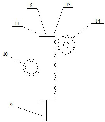
[0043] Such as Figure 6 As shown, the portable optical fiber jumper reel device according to the embodiment of the present invention is a further improvement to Embodiment 1: the sticker box includes a groove body 23, and the rear side of the groove body 23 is connected to the electric push rod 15 , the front side of the tank body 23 is provided with openings, the movable baffle plate 24 is arranged in the described tank body 23, and the rear side of the movable baffle plate 24 is fixedly provided with two support rods 25, and the two support rods 25 are all connected from the The through hole on the tank body 23 passes through, and the end of the support rod 25 is connected with a nut 26, and the spring 27 is sleeved on the support rod 25, and the spring 27 is located between the movable baffle plate 24 and the groove. Between the body 23; the second travel switch 28 is arranged on the groove body 23, and the end of the second travel switch 28 is flush with the front side of...


PUM


Abstract

The invention discloses a portable optical fiber patch cord coiling device, and belongs to the technical field of intelligent power grid optical fiber laying. The device comprises a box body and a box cover, one sides of the box body and the box cover are hinged, and the box body is internally provided with a coiling assembly used for coiling an optical fiber patch cord, a guide assembly used for arranging the optical fiber patch cord, and a first fixing assembly used for fixing the inner side of the coiled optical fiber patch cord; and the inner side of the box cover is provided with a second fixing assembly used for fixing the outer side of the coiled optical fiber patch cord. The coiling assembly comprises a driving motor, a rotating shaft and a plurality of coiling blocks, the driving motor drives the rotating shaft to rotate, the multiple coiling blocks are evenly distributed at the peripheral side of the rotating shaft, a gap is reserved between every two adjacent coiling blocks, and the outer surfaces of the coiling blocks are cambered surfaces. According to the portable optical fiber patch cord coiling device, the coiling length of the optical fiber patch cord can be self-defined, coiling can be neat, the coiled optical fiber patch cord can be fixed, and the phenomenon that scattered turns are disordered in the paying-off process is avoided.

Description

technical field [0001] The invention relates to the technical field of smart grid optical fiber layout, in particular to a portable optical fiber jumper coiling device. Background technique [0002] The smart grid is the intelligence of the grid, also known as "grid 2.0", which is based on an integrated, high-speed two-way communication network, through advanced sensing and measurement technology, advanced equipment technology, advanced control methods and The application of advanced decision support system technology achieves the goals of reliability, security, economy, efficiency, environmental friendliness and safe use of the power grid. Its main features include self-healing, incentives and protection of users, resistance to attacks, and power quality that meets user needs , allowing the access of various forms of power generation, starting the power market and optimizing and efficient operation of assets. [0003] In the process of smart grid construction, optical fibe...

Claims


Application Information

Patent Timeline
IPC IPC(8): B65H75/44B65H54/28
CPCB65H75/4405B65H75/4471B65H75/4473B65H54/28B65H2701/32
Inventor 王珂姜红军尹璐璐邱国林李天杰崔岳峰王静赵鹤熙刘国庆
Owner 国网河南省电力公司社旗县供电公司
Why Eureka
Try Eureka