Acoustic parameter measuring device, method and system

An acoustic parameter, measuring device technology, applied in measuring devices, scientific instruments, material analysis using sonic/ultrasonic/infrasonic waves, etc., can solve the problems of poor measurement accuracy, inability to fix the shape of the film, and troublesome production

Pending Publication Date: 2021-07-06
广东省医疗器械质量监督检验所
View PDF6 Cites 1 Cited by
  • Summary
  • Abstract
  • Description
  • Claims
  • Application Information

AI Technical Summary

Problems solved by technology

This method requires a large number of samples, which is troublesome to make,

Method used


Image

  • Acoustic parameter measuring device, method and system
  • Acoustic parameter measuring device, method and system
  • Acoustic parameter measuring device, method and system

Examples


Embodiment 1

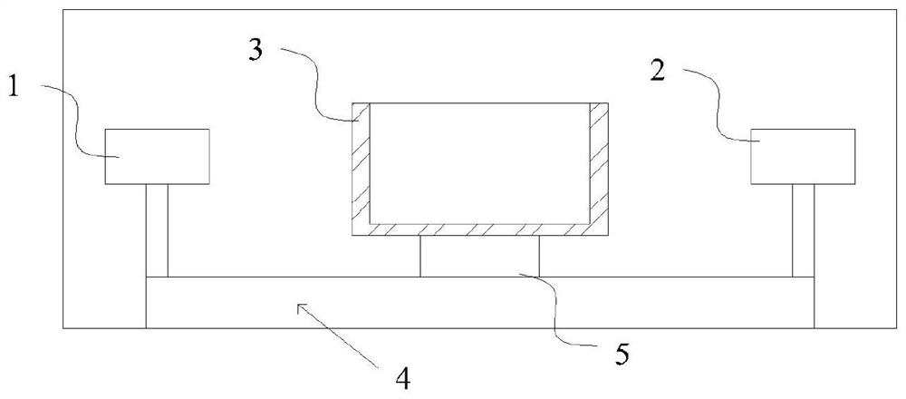
[0041] Such as Figure 1-2 As shown, the present embodiment provides an acoustic parameter measuring device, including an ultrasonic transmitting mechanism 1 and an ultrasonic receiving mechanism 2; there is a space with a fixed distance between the ultrasonic transmitting mechanism 1 and the ultrasonic receiving mechanism 2; it also includes: a sample container 3, A wall surface perpendicular to the plane wave acoustic beam path is provided, and at least two container parts with different inner cavity thicknesses are provided; there is relative movement between the sample container 3 and the plane wave acoustic beam path, which is used to change the direction of the sample container 3 in the plane wave acoustic beam path direction Among them, before and after the relative movement, the wall surface of the sample container passed by the plane wave sound beam path is perpendicular to the plane wave sound beam path, and the sum of the wall thicknesses of the sample container 3 in...

Embodiment 2

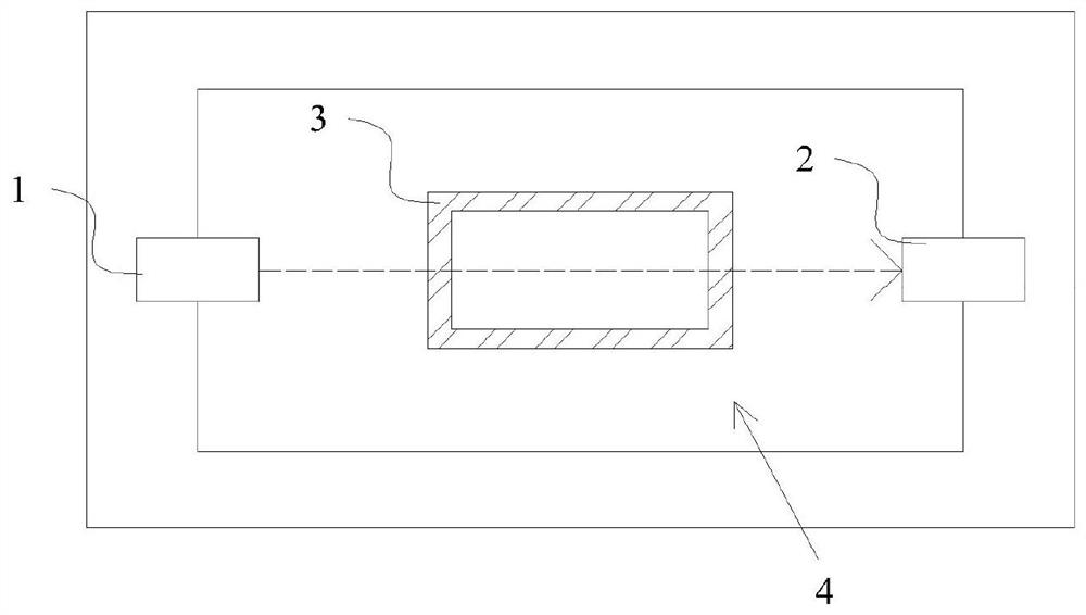
[0052] Such as Figure 3-4 As shown, the difference between this embodiment and Embodiment 1 is that the ultrasonic transmitting mechanism 1 and the ultrasonic receiving mechanism 2 maintain a fixed distance to perform synchronous movement, while the sample container 3 remains stationary.

[0053] The moving device 5 is a turntable, and it is set to deflect 90° around its central axis each time it rotates. Two brackets are arranged on the surface circumference of the turntable, and the connecting line of the two brackets passes through the central axis of the turntable to connect to the ultrasonic emitting mechanism respectively. 1 and ultrasonic receiving mechanism 2. The sample container 3 is arranged directly above the center of the turntable through the positioning mechanism 4, and the central axis of the turntable passes through the geometric center of the bottom side of the sample container 3, so that the plane wave sound beam path between the ultrasonic transmitting mec...

Embodiment 3

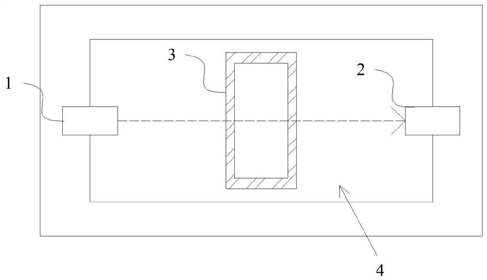
[0055] Such as Figure 5-6 As shown, the difference between this embodiment and Embodiment 1 lies in the shape and movement mode of the sample container 3 . The horizontal section of the sample container 3 in this embodiment is in a "convex" shape, and the thickness of the pulse passing through the sample container 3 is changed by means of translation.

[0056] The ultrasonic transmitting mechanism 1 and the ultrasonic receiving mechanism 2 are arranged on the positioning mechanism 4, and the surface of the center position of the positioning mechanism 4 is provided with two parallel guide rails to guide the moving device 5 to move back and forth. The moving device 5 is two moving brackets, one end of the two moving brackets is respectively connected to two guide rails, and the other end is fixed to the bottom of the sample container 3, and the sample container 3 is driven by the moving device 5 to move forward and backward, and the plane wave sound beam The path is perpendicu...


PUM


Abstract

The invention relates to the field of detection equipment, in particular to an acoustic parameter measuring device, method and system. The acoustic parameter measuring device comprises an ultrasonic transmitting mechanism and an ultrasonic receiving mechanism, an ultrasonic transmitting mechanism and an ultrasonic receiving mechanism; an interval space with a fixed distance D exists between the ultrasonic transmitting mechanism and the ultrasonic receiving mechanism; the device further comprises a sample container which is provided with a wall surface vertical to a plane wave sound beam path and comprises at least two container parts with different inner cavity thicknesses; relative movement exists between the sample container and a plane wave sound beam path and is used for changing the thickness of the sample container in the direction of the plane wave sound beam path; and before and after the relative movement, the wall surface of the sample container penetrated by the plane wave acoustic beam path is perpendicular to the plane wave acoustic beam path, and the sum of the wall surface thickness of the sample container in the direction of the plane wave acoustic beam path is kept unchanged.

Description

technical field [0001] The present invention relates to the field of detection equipment, and more specifically, to an acoustic parameter measurement device, method and system. Background technique [0002] Standard YY 0299-2016 "Medical Ultrasonic Couplant" and GB / T15261-2008 "Measurement Method for Acoustic Properties of Ultrasonic Imitation Tissue Materials" disclose the measurement methods of acoustic parameters such as acoustic impedance, sound velocity, and sound attenuation. This method is more suitable for the test of solid substances. When measuring water-based gel or liquid, it is necessary to put the water-based gel or liquid into a tubular container, seal the film on both sides, and make two long and short samples respectively, ignoring the film For the influence on the results, the calculation formulas of sound velocity and sound attenuation coefficient of solid matter are followed. This method requires a large number of samples, which is troublesome to make, a...

Claims


Application Information

Patent Timeline
IPC IPC(8): G01N29/024G01N29/032G01N29/22
CPCG01N29/024G01N29/032G01N29/222G01N2291/011G01N2291/015
Inventor 刘智伟林鸿宁杨航
Owner 广东省医疗器械质量监督检验所
Why Eureka
Try Eureka