Automatic feeding and discharging high-speed chip mounter

An automatic feeding and placement machine technology, applied in electrical components, printed circuit manufacturing, electrical components, etc., can solve the problems of poor matching between placement machines and pads at the same time.

Inactive Publication Date: 2021-07-06
周创
View PDF0 Cites 1 Cited by
  • Summary
  • Abstract
  • Description
  • Claims
  • Application Information

AI Technical Summary

Problems solved by technology

[0004] The purpose of the present invention is to provide a high-speed chip mounter with automatic feeding and discharging, so as to solve the problem that its feeding device cannot cooperate with the chip mounter in the above-mentioned background technology, and feeds materials into the chip mounter, causing the chip mounter and the pad The problem of poor coordination at the same time

Method used


Image

  • Automatic feeding and discharging high-speed chip mounter
  • Automatic feeding and discharging high-speed chip mounter
  • Automatic feeding and discharging high-speed chip mounter

Examples


Embodiment Construction

[0026] The following will clearly and completely describe the technical solutions in the embodiments of the present invention with reference to the accompanying drawings in the embodiments of the present invention. Obviously, the described embodiments are only some, not all, embodiments of the present invention. Based on the embodiments of the present invention, all other embodiments obtained by persons of ordinary skill in the art without making creative efforts belong to the protection scope of the present invention.

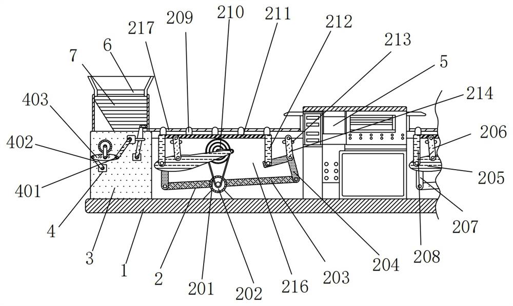
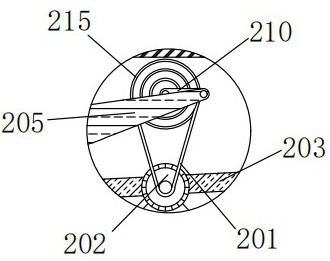
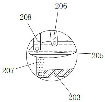
[0027] see Figure 1-6 , the present invention provides a technical solution, a high-speed placement machine with automatic feeding and discharging, including a workbench 1, a first box 3 is installed on the left side of the top of the workbench 1, and a first box 3 is installed on the top of the first box 3. The second box body 7, the top of the second box body 7 is connected with the feed hopper 6, the top right side of the workbench 1 is equipped with a pla...


PUM


Abstract

The invention discloses an automatic feeding and discharging high-speed chip mounter which comprises a workbench, a first box body is installed on the left side of the top of the workbench, a chip mounter is installed on the right side of the top of the workbench, and a chip pushing assembly is arranged on the left side of the top of the workbench. Through the rotary connection relation between a second short handle and a third short handle, the fixed relation between a vertical block and a square block, and empty grooves processed in the front and rear end faces of a second box body, the vertical block shifts a bonding pad to enable the bonding pad to leave the second box body, so that a chip mounter is matched with the bonding pad at the same time, the chip mounter better carries out chip mounting on the bonding pad, the control is convenient, a second short rod is rotationally connected with an elliptical plate, and a sixth short rod is rotationally connected with a first cross rod through a short seat, so that the elliptical plate is driven by a second motor to enable a second cross rod to operate along an elliptical track, and then the bonding pad plate is continuously fed for equal time through a sliding rail.

Description

technical field [0001] The invention relates to the technical field of automatic feeding and discharging high-speed placement machines, in particular to an automatic feeding and discharging high-speed placement machines. Background technique [0002] The placement machine is also called "mounting machine" and "surface mount system". In the production line, it is configured after the dispensing machine or screen printing machine, and the surface mount components are accurately placed on the PCB by moving the placement head. A device on the pad is divided into two types: manual and fully automatic, so a high-speed placement machine with automatic feeding and discharging is needed. [0003] The automatic feeding and discharging high-speed placement machine in the prior art, its feeding device cannot cooperate with the placement machine, and feeds materials into the placement machine, resulting in a poor effect of simultaneous cooperation between the placement machine and the pa...

Claims


Application Information

Patent Timeline
Patent Type & Authority Applications(China)
IPC IPC(8): H05K13/04H05K3/34
CPCH05K3/341H05K13/0417H05K13/0465
Inventor 周创
Owner 周创
Why Eureka
Try Eureka