Medical traumatic orthopedic traction device based on big data
A trauma orthopedics and traction device technology, applied in the medical field, can solve the problems of restricting the use of traction devices, lack of patient care training, time-consuming and labor-intensive, etc.
- Summary
- Abstract
- Description
- Claims
- Application Information
AI Technical Summary
Problems solved by technology
Method used
Image
Examples
Embodiment 1
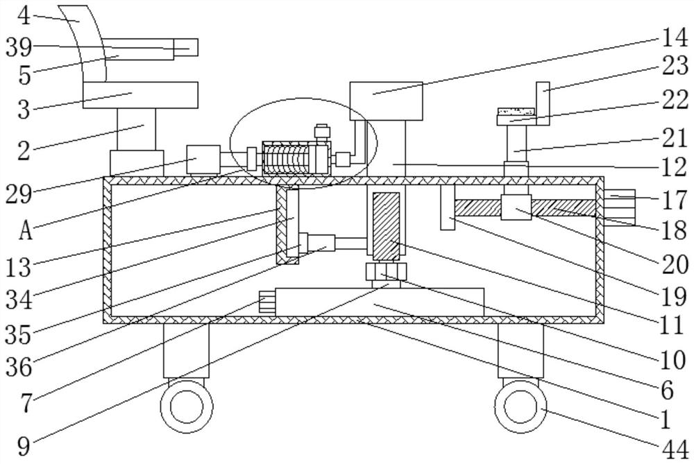
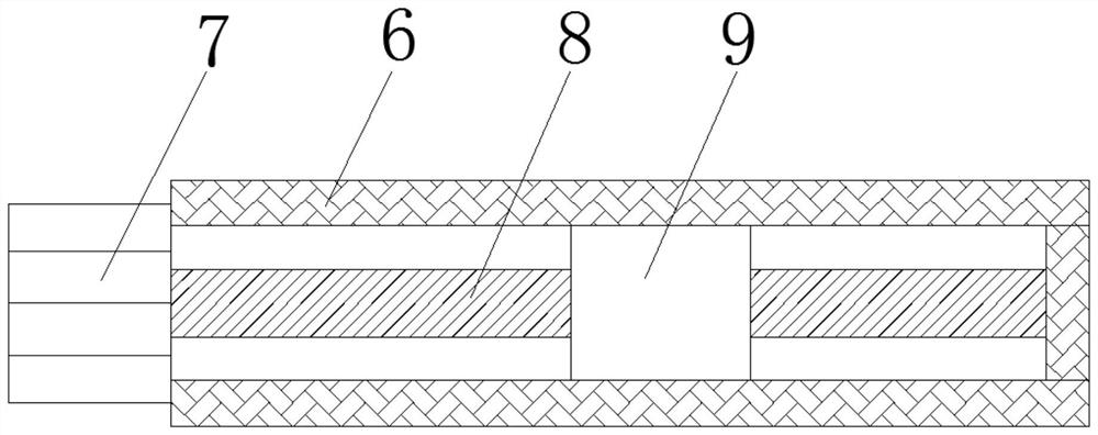
[0029] See Figure 1-7According to an embodiment of the present invention, a large data medical trauma traction device comprising a base 1, and a top portion of the base 1 is fixedly coupled with an electric telescoping rod one 2, and the top end of the electric telescoping rod 1 2 fixed connection There is a seat plate 3, and the top end of the seat plate 3 is fixedly coupled with a back plate 4, and the back plate 4 is fixed to one side of the seat plate 3 fixing the armrest 5, and the inner bottom end of the base 1 is fixed to U The type frame 6, one end of the U-shaped frame 6 fixedly connected to the motor one 7, the output shaft of the motor one 7 fixedly connected to the wire 8, the screw 8 away from the motor one 7 and the end The U-axis 6 inner wall activity is connected, the surface of the screw 8 is connected to the screw slider 9, and the top end of the screw slider 9 is fixedly connected to the motor II 10, and the output shaft of the motor II 10 is fixedly connected. ...
Embodiment 2
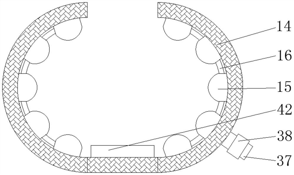
[0032] See Figure 1-7 For the limit mechanism, the limit mechanism includes a restricted groove 34, a limit slider 35, and a telescopic rod 36, and a restricted groove 34 is provided on one side of the fixing plate 13, the restricted groove 34 The internal sliding connection has a restricted slider 35, and the restricted slider 35 is fixed between the threaded sleeve 12, and the exhaust mechanism includes an exhaust pipe 37 and a valve for the exhaust mechanism. 38. On one side of the airbag 15 is fixedly connected to the exhaust pipe 37, the exhaust pipe 37 is mounted on the exhaust pipe 37, and for the control mechanism, the control mechanism includes a control panel 39, one end of the armrest 5. The control panel 39 is fixedly connected, and the motor one 7 is electrically connected to the control panel 39 with the motor 31 and the motor 3 17.
[0033] According to the above scheme of the present invention, the limit mechanism is provided, not only to the surface of the threade...
Embodiment 3
[0035] See Figure 1-7 For the sliding mechanism, the sliding mechanism includes a slide rail one 40 and a rail 2 41, and the top of the base 1 has a slide rail one 40 and a rail 2 41, and the inside of the slide rail one 40. The threaded sleeve 12 is slidable, and the inside of the sliding rail 2 41 is slidably connected to the electric telescoping rod 2 21, and for the leg support seat 14, the internal top end of the leg support seat 14 is fixedly connected. Rubber pad 42.
[0036] With the above scheme of the present invention, the rubber pad 42 can be provided before the friction between the leg and the leg support, facilitates the fixation of the leg, and can also protect the leg.
PUM
 Abstract
Description
Claims
Application Information
 - R&D
- Intellectual Property
- Life Sciences
- Materials
- Tech Scout
- Unparalleled Data Quality
- Higher Quality Content
- 60% Fewer Hallucinations
Browse by: Latest US Patents, China's latest patents, Technical Efficacy Thesaurus, Application Domain, Technology Topic, Popular Technical Reports.
© 2025 PatSnap. All rights reserved.Legal|Privacy policy|Modern Slavery Act Transparency Statement|Sitemap|About US| Contact US: help@patsnap.com


