Aluminum magnesium alloy power line groove sheet metal machining equipment and machining method

A technology of aluminum-magnesium alloy and processing equipment, which is applied in the field of electric power engineering, can solve the problems of reducing the processing efficiency of aluminum-magnesium alloy power line slots, affecting the quality of aluminum-magnesium alloy power line slots, and increasing processing costs, so as to improve the shaping effect, avoid rebound, The effect of improving the yield rate

Active Publication Date: 2021-07-09
广东海彬线槽有限公司
View PDF7 Cites 1 Cited by
  • Summary
  • Abstract
  • Description
  • Claims
  • Application Information

AI Technical Summary

Problems solved by technology

[0003] Aluminum-magnesium alloy power ducts are generally processed by sheet metal, that is, the aluminum-magnesium alloy plate is folded and formed through a mold. The aluminum-magnesium alloy power line duct needs to be folded multiple times, which greatly reduces the processing efficiency of the aluminum-magnesium alloy power line duct and increases the processing cost. At the same time, it is impossible to maintain the pressure of the formed aluminum-magnesium alloy, which is easy The aluminum-magnesium alloy power line trough has a rebound phenomenon after forming, which affects the quality of the aluminum-magnesium alloy power line trough

Method used


Image

  • Aluminum magnesium alloy power line groove sheet metal machining equipment and machining method
  • Aluminum magnesium alloy power line groove sheet metal machining equipment and machining method
  • Aluminum magnesium alloy power line groove sheet metal machining equipment and machining method

Examples


Embodiment Construction

[0026] In order to make the technical means, creative features, goals and effects achieved by the present invention easy to understand, the present invention will be further described below in conjunction with specific illustrations. It should be noted that, in the case of no conflict, the embodiments in the present application and the features in the embodiments can be combined with each other.

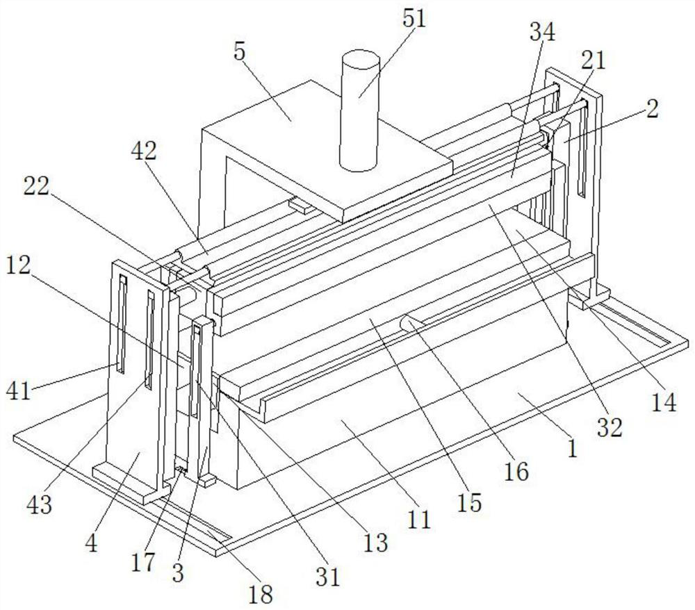
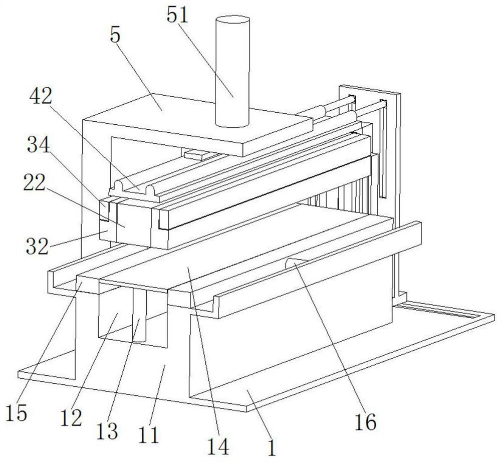
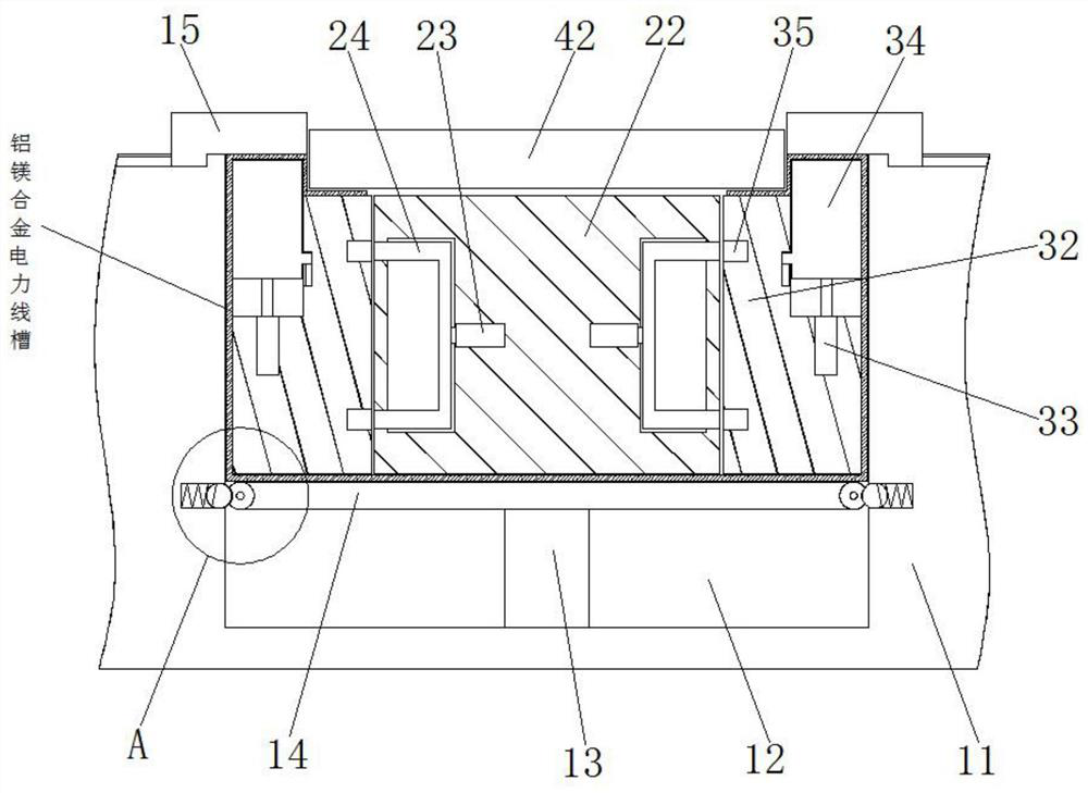
[0027] Such as Figure 1 to Figure 6 As shown, an aluminum-magnesium alloy power line groove sheet metal processing equipment includes a base 1, a fixed platform 11 is arranged on the base 1, a mold cavity 12 is arranged on the top of the fixed platform 11, and a number of number ones are arranged in the mold cavity 12 Spring bar 13, the top of No. 1 spring bar 13 is provided with supporting plate 14, on the fixed table 11 and is positioned at the both sides of die groove 12, be provided with bead 15, the top of bead 15 is flush with the top of supporting plate 14, fixed table The t...


PUM


Abstract

The invention relates to the field of electric power engineering, in particular to aluminum magnesium alloy power line groove sheet metal machining equipment and a machining method. The aluminum magnesium alloy power line groove sheet metal machining equipment comprises a base, a fixing table is arranged on the base, a die groove is formed in the top of the fixing table, a plurality of first spring rods are arranged in the die groove, and a supporting plate is arranged at the tops of the first spring rods. Pressing strips are arranged on the fixing table and located on the two sides of the die groove, the tops of the pressing strips are flush with the top of the supporting plate, first air cylinders are arranged on the two sides of the top of the fixing table correspondingly, and the output ends of the first air cylinders are fixedly installed on the correspondingly-arranged pressing strips correspondingly. First supports are symmetrically arranged on the base and located at the two ends of the fixing table, first sliding grooves are formed in the first supports, a first pressing block of a rectangular structure is arranged between the first supports, and the two ends of the first pressing block are connected into the first sliding grooves correspondingly in a sliding mode. According to the aluminum magnesium alloy power line groove sheet metal machining equipment and the machining method, compression molding of aluminum magnesium alloy power line grooves can be rapidly and efficiently achieved, and the aluminum magnesium alloy power line groove sheet metal machining equipment and the machining method are suitable for popularization.

Description

technical field [0001] The invention relates to the field of electric power engineering, in particular to a sheet metal processing equipment and a processing method of an aluminum-magnesium alloy power line groove. Background technique [0002] Wire trough, also known as wiring trough, wiring trough, line trough, is used to organize power lines, data lines and other wires according to specifications, and fix electrical appliances on the wall or ceiling. In modern power engineering, in order to ensure For the strength of the trunking, alloy trunking is often used, such as aluminum-magnesium alloy trunking. This alloy trunking is also called high-voltage bus duct. It is used in large-scale substations, power supply systems, and self-owned power plants of large enterprises. It replaces the traditional bare row wiring method. In addition to being safe, beautiful, and reliable, it can also greatly reduce the number of power outage maintenance because the high-voltage busway shell...

Claims


Application Information

Patent Timeline
Patent Type & Authority Applications(China)
IPC IPC(8): B21D21/00B21D5/16B21D19/08B21D45/06
CPCB21D21/00B21D5/16B21D19/08B21D45/06
Inventor 李庆超
Owner 广东海彬线槽有限公司
Why Eureka
Try Eureka