Supercharge Your Innovation With Domain-Expert AI Agents!

Control method for empennage of unmanned aerial vehicle

A control method and technology of unmanned aerial vehicles, which are applied in aircraft control, aircraft parts, aircraft stability and other directions, can solve the problems of flight resistance not being controlled to a minimum, increased energy consumption, and inability to adjust control, so as to improve handling performance and reduce resistance. , the effect of ensuring safety

Inactive Publication Date: 2021-07-09
CHANGSHU INSTITUTE OF TECHNOLOGY
View PDF0 Cites 0 Cited by
  • Summary
  • Abstract
  • Description
  • Claims
  • Application Information

AI Technical Summary

Problems solved by technology

[0003] The existing UAV tail control method makes the position of the UAV tail relative to the main body of the UAV generally fixed and cannot be adjusted and controlled.
Changes in the external flight environment such as the flight speed, air pressure, air temperature, and wind speed of the UAV, as well as the adjustment of the flight attitude, the lift moment of the air wing also changes in real time, and the position of the tail relative to the main body of the UAV cannot be adjusted, which will cause The torque provided by the empennage cannot best balance the aircraft, which leads to a decrease in the control performance of the aircraft, and the safety cannot be guaranteed, and the flight resistance is not controlled to the minimum, which increases energy consumption and affects the cruising range of the drone.

Method used


Image

  • Control method for empennage of unmanned aerial vehicle
  • Control method for empennage of unmanned aerial vehicle

Examples


Embodiment Construction

[0028] The technical solutions in the embodiments of the present invention will be clearly and completely described below in conjunction with the accompanying drawings in the present invention. Apparently, the described embodiments are only illustrative partial implementations of the present invention, and are not intended to limit the scope of the present invention. , any equivalent changes and modifications made by those skilled in the art without departing from the concepts and principles of the present invention shall fall within the protection scope of the present invention.

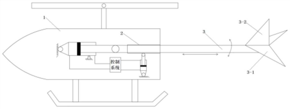
[0029] The invention provides a method for controlling the tail of an unmanned aerial vehicle, such as figure 1 As shown, the empennage 3 has a horizontal empennage 3-1, a vertical empennage 3-2 and a sliding rod, a part of the sliding rod is arranged in the UAV main body 1, and one of the sliding sleeves of the sliding rod in the UAV main body 1 is provided with Sliding cylinder 2, the drone main b...


PUM


Abstract

The invention belongs to the technical field of empennages of unmanned aerial vehicles and relates to anempennage assembly of an unmanned aerial vehicle. The empennage assembly comprises a horizontal empennage, a vertical empennage and a sliding rod, a part of the sliding rod is arranged in an unmanned aerial vehicle body, and the sliding rod in the unmanned aerial vehicle body is slidably sleeved with a sliding barrel; a horizontal oil cylinder and a vertical oil cylinder are arranged in the unmanned aerial vehicle body, a piston rod of the horizontal oil cylinder is hinged to the end of the sliding rod, the vertical oil cylinder is hinged to the middle of the sliding barrel. The horizontal oil cylinder and the vertical oil cylinder are both controlled by a control system, the control system is a servo hydraulic system, and the servo hydraulic system is provided with a servo pump. One path of an oil outlet of the servo pump is communicated with an oil tank through a first pilot overflow valve and an oil radiator, and the other path of the oil outlet of the servo pump is connected with a first two-position three-way electromagnetic directional valve, a second two-position three-way electromagnetic directional valve and an energy accumulator. The horizontal oil cylinder and the vertical oil cylinder are controlled in a closed-loop mode, act in sequence through the control system and do not interfere with each other, and the reliability of the control system is improved.

Description

technical field [0001] The invention relates to a method for controlling the UAV tail, in particular to a real-time control method for the relative position of the UAV tail relative to the UAV body. Background technique [0002] The tail of the drone mainly plays a balancing role. The drone relies on the wings to generate lift to fly, but the center of gravity of the lift of the drone often does not coincide with the center of gravity of the aircraft. Moment, and then make the aircraft pitch up or pitch down, in order to balance this moment, the horizontal tail is required to generate an opposite moment to balance the aircraft. Another important function of the tail of the UAV is to control the deflection of the aircraft. Using the principle of aerodynamics, the horizontal tail can be used to control the pitch flight of the UAV, and the vertical tail is used to control the left and right deflection flight of the UAV. [0003] In the existing control method for the tail of t...

Claims


Application Information

Patent Timeline
Patent Type & Authority Applications(China)
IPC IPC(8): B64C5/10
CPCB64C5/10
Inventor 梁昌平
Owner CHANGSHU INSTITUTE OF TECHNOLOGY
Features
  • R&D
  • Intellectual Property
  • Life Sciences
  • Materials
  • Tech Scout
  • Unparalleled Data Quality
  • Higher Quality Content
  • 60% Fewer Hallucinations
Learn More