
Water purifying equipment with directional selective reverse osmosis filtering structure

A technology of water purification equipment and filtration structure, applied in water/sewage treatment equipment, osmosis/dialysis water/sewage treatment, water/sewage treatment, etc. The concentration ratio of wastewater to purified water cannot be further improved, etc.

Active Publication Date: 2021-07-09
上海求越实业有限公司
View PDF11 Cites 0 Cited by
  • Summary
  • Abstract
  • Description
  • Claims
  • Application Information

AI Technical Summary

Problems solved by technology

[0004] In the prior art, due to the limitation of the principle of reverse osmosis, while producing clean water, waste water must be discharged. If the ratio of waste water to clean water is higher High, the water waste is serious, and this ratio is limited by the pressure difference that the reverse osmosis membrane can withstand. The smaller the bearing capacity, the smaller the pressure difference that can be loaded, and the concentration ratio of wastewater to purified water cannot be further increased. As a result, the amount of wastewater is large, and the waste of water resources is a major problem in the promotion of reverse osmosis water purification equipment; after long-term use of the semi-permeable membrane, there is also a certain probability of forming scale, which affects the water purification effect of the semi-permeable membrane. It is difficult to remove the semi-permeable membrane for flushing, and it is easy to damage the semi-permeable membrane. Therefore, direct replacement is generally used. For source water that is prone to scaling, frequent replacement cycles will affect the use

Method used


Image

  • Water purifying equipment with directional selective reverse osmosis filtering structure
  • Water purifying equipment with directional selective reverse osmosis filtering structure
  • Water purifying equipment with directional selective reverse osmosis filtering structure

Examples


Embodiment Construction

[0022] Next, the technical solutions in the embodiments of the present invention will be apparent from the embodiment of the present invention, and it is clearly described, and it is understood that the described embodiments are merely embodiments of the present invention, not all of the embodiments. Based on the embodiments of the present invention, there are all other embodiments obtained without making creative labor without making creative labor premises.

[0023] See Figure 1-5 The present invention provides a technical solution:

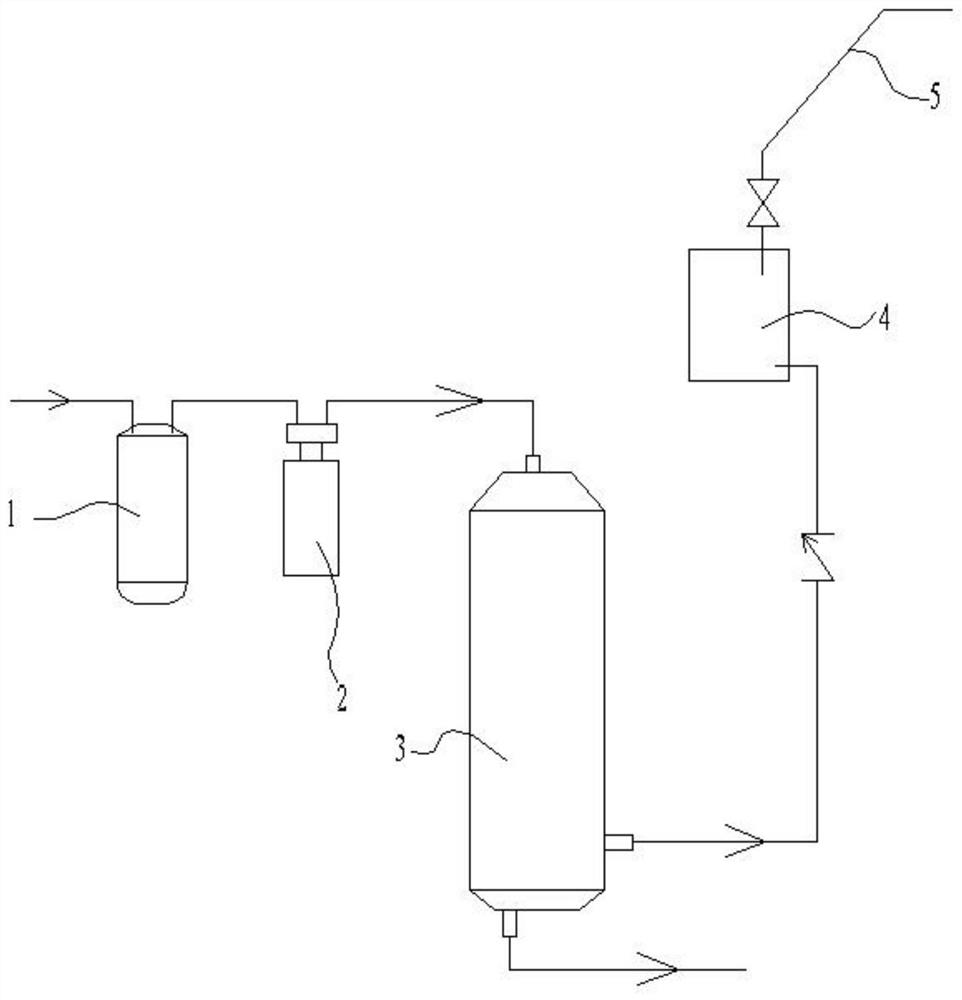
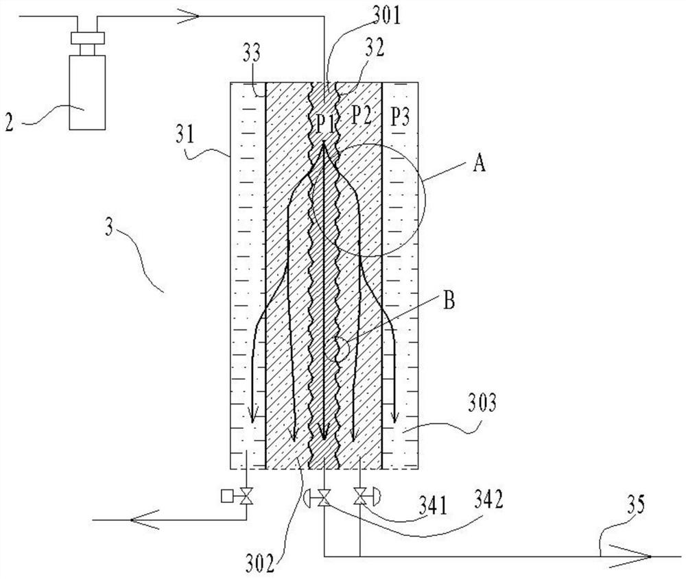
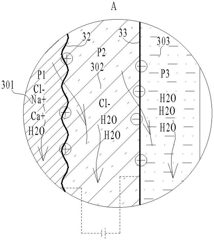
[0024]A water purification apparatus with a directional selective reverse osmosis filter comprising an inlet filter element 1, a pressurizing pump 2, a reverse osmosis filter 3, an inlet filter element 1, a booster pump 2, and the reverse osmosis filter 3 sequentially passed through a water pipe. Let together, the reverse osmosis filter 3 includes a housing 31, a first semipermeable film 32, a second semiperm film 33, and a bleed opening 35, and th...


PUM


Abstract

The invention discloses water purification equipment with a directional selective reverse osmosis filter structure, which comprises an inlet filter element, a booster pump and a reverse osmosis filter element, which are sequentially connected together through water pipes; the reverse osmosis filter element comprises a shell, a first semi-permeable membrane, a second semi-permeable membrane and a discharge port, wherein the interior of the shell is divided into three flow channels by a first semi-permeable membrane and a second semi-permeable membrane in sequence, namely a first flow channel, a second flow channel and a third flow channel; one end of the first runner serves as a reverse osmosis filter element inlet, and the other end of same is connected to the discharge port; a first pressure regulating valve is arranged on a pipeline through which the first flow channel is connected to the discharge port; one end of the second flow channel is closed, one end is connected to the discharge port, a second pressure regulating valve is arranged on a pipeline for connecting the second flow channel to the discharge port, one end of the third flow channel is closed, and the other end of same is used as a purified water outlet of the reverse osmosis filter element.

Description

Technical field [0001] The present invention relates to the field of water purification technologies, specifically a water purification apparatus with a directional selective reverse osmosis filter structure. Background technique [0002] The reverse osmosis water purification equipment is a purification apparatus for a more clean water, which has been treated with tap water or river water, which can be directly driven, and its core is the reverse osmosis effect of reverse osmosis membrane. [0003] The reverse osmosis membrane is a film having a microporous film, also known as a semipermeable membrane, and water from one side can pass through the pressure to reach the low concentration state of the other side, reach the purified water, concentrated wastewater the goal of. Because continuity works and does not need to be heated, the application is getting wider. [0004] In the prior art, because of the limitations of reverse osmosis, while outputting water purification, the disc...

Claims


Application Information

Patent Timeline
IPC IPC(8): C02F1/44
CPCC02F1/441C02F2201/002C02F2303/14Y02A20/131
Inventor 戴庆云戴庆华
Owner 上海求越实业有限公司
Learn More