A direct heating type multi-stage serial turbulent bed pyrolysis stripping furnace in a combustion flame furnace

A flame furnace and turbulent bed technology, which is applied in the field of solid waste treatment equipment, can solve the problems such as the inability of pyrolysis solid residues to meet the requirements of ultra-clean emission environmental protection indicators, the large difference in treatment effects, and the small treatment scale of pyrolysis furnaces. The effect of improving the yield of organic matter conversion and recovery, improving the efficiency of heat supply and heat absorption, and improving the efficiency of heat utilization

Active Publication Date: 2022-04-12
NINGBO LIANTONG EQUIP MFG
View PDF10 Cites 0 Cited by
  • Summary
  • Abstract
  • Description
  • Claims
  • Application Information

AI Technical Summary

Problems solved by technology

[0007] The pyrolysis method varies greatly depending on the pyrolysis reactor (pyrolysis furnace) technology. The "batch" pyrolysis furnace can feed materials once and discharge slag once, so it cannot be continuously produced, and the processing scale of the pyrolysis furnace is small; " The continuous type pyrolysis furnace has a small processing scale, and the continuous operability is not high due to various factors. At present, both "intermittent" and "continuous" pyrolysis furnaces use organic solid waste in the furnace, heat carrier (External heat supply) Outside the furnace, the "indirect" heat supply and pyrolysis method in which the organic solid waste in the jacket is in direct contact with the heat has low heat transfer efficiency and low heat absorption efficiency, resulting in low heat utilization efficiency and heat loss. Problems such as slow decomposition reaction speed, long reaction time, high energy consumption, pyrolysis solid residues cannot meet the requirements of ultra-clean emission environmental protection indicators, etc.

Method used


Image

  • A direct heating type multi-stage serial turbulent bed pyrolysis stripping furnace in a combustion flame furnace
  • A direct heating type multi-stage serial turbulent bed pyrolysis stripping furnace in a combustion flame furnace
  • A direct heating type multi-stage serial turbulent bed pyrolysis stripping furnace in a combustion flame furnace

Examples


Embodiment 1

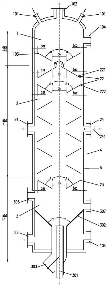
[0040] A direct heating type multi-stage serial turbulent bed pyrolysis stripping furnace in a combustion flame furnace, see figure 1 , including a furnace shell 4, the furnace shell 4 includes an upper furnace 1, a middle furnace 2, and a lower furnace 3 connected to each other from top to bottom in sequence, and the furnace shell 4 is provided with a refractory and heat-insulating lining 5.

[0041] The top or upper side of the upper furnace 1 is provided with n (n≥1) organic solid waste material inlets 101, n (n≥1) gaseous organic matter pyrolysis stripping products and gaseous mixture outlets 102 of high-temperature flue gas, and material inlet distribution Plate 103 and manhole 104.

[0042] The angle α between the upper surface of the material inlet distribution plate 103 and the center line of the furnace shell 4 is any angle between 0-180°, and it is at the bottom (0°<α ≤ 90°) or top of the central area (90°< α < 180°) open a notch with a width or diameter of a0 (a0≥0...

Embodiment 2

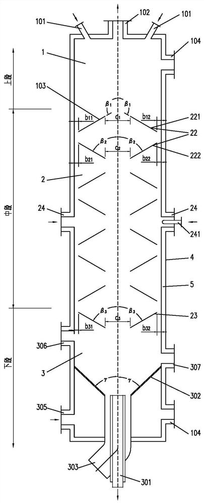
[0085] see figure 2 , a kind of direct heating type multi-stage serial turbulent bed pyrolysis and stripping furnace in a combustion flame furnace, comprising a vertical square structure furnace shell 4, the furnace shell 4 includes an upper section furnace 1, a middle section furnace 2 and a furnace connected to each other The lower furnace 3 has a rectangular cross-sectional shape but unequal cross-sectional area. The furnace shell 4 of the upper furnace 1 has a section length x width of 4000x2500mm, a straight section height of 3000mm, and a refractory and heat-insulating lining 5 with a thickness of 150mm; the furnace of the middle furnace 2 The inner diameter of the shell 4 is 4000x2000mm in length and width, the height of the straight section is 24000mm, and the thickness of the refractory and heat-insulating lining 5 is 250mm; 5 The thickness is 400mm.

[0086] Two organic solid waste material inlets 101 are symmetrically arranged on both sides of the top of the upper...

Embodiment 3

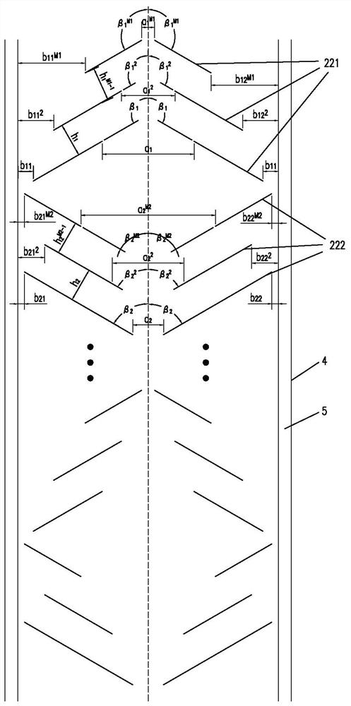
[0091] The difference from Example 1 is that the structure of the turbulent micro-reaction bed 22 is different. see image 3 , each group of turbulent micro-reaction beds 22 can also be composed of M1 (M1≥2, and M1≤N / 2 and take an integer) block upper guide plate 221 and M2 (M2≥2, and M2≤N / 2 and take Integer) blocks of lower deflectors 222, which are arranged symmetrically or asymmetrically in a stepped shape with the center line of the furnace shell 4 as the central axis, and M1 of each group and two adjacent groups of turbulent micro-reaction beds 22 and M2 can be the same number or different numbers; the area between the first upper guide plate 221 and the first lower guide plate 222 of each group constitutes the main reaction zone, and the M1 upper guide plate of each group The area or annular gap between the flow plate 221 and the inner wall of the refractory and heat-insulating lining 5 can form several secondary reaction zones through different openings on the upper fl...


PUM


Abstract

The present application relates to the field of solid waste treatment, and in particular to a multi-stage serial turbulent bed pyrolysis and stripping furnace with direct heat feeding in a combustion flame furnace, which includes a furnace shell, and the furnace shell includes an upper furnace connected to each other , the middle furnace, the lower furnace and the refractory insulation lining; the upper furnace has an organic solid waste material inlet and a gaseous mixture outlet; the middle furnace has several groups of turbulent micro-reaction beds connected in series; the lower furnace has a fuel burner , pressure and temperature gas inlet and residue outlet; the fuel is burned by the fuel burner to generate high-temperature flue gas flowing from bottom to top and directly contacting organic solid waste to provide heat. The present application has the effect of improving the pyrolysis efficiency of the reactor.

Description

technical field [0001] The present application relates to the field of solid waste treatment equipment, in particular to a multi-stage serial turbulent bed pyrolysis and stripping furnace directly feeding heat in a combustion flame furnace. Background technique [0002] With the acceleration of my country's economic development and urbanization, the consumption of resources is increasing, the output of various wastes is increasing, the forms of waste are diversified, and problems such as soil and groundwater pollution are becoming more and more serious. National environmental protection regulations stipulate that solid wastes containing organic matter (i.e. organic solid wastes, most of which are hazardous wastes) need to be reduced and treated in a harmless manner to meet environmental protection emission requirements. Appropriate technology can be used to realize resource recovery Utilization, the polluted soil needs to be repaired and treated to meet the soil quality requ...

Claims


Application Information

Patent Timeline
Patent Type & Authority Patents(China)
IPC IPC(8): C10B53/00C10B53/02
CPCC10B53/00C10B53/02Y02E50/10
Inventor 郭文元郭强连卫平连海峰周鹤群蔡丽萍蔡文婷邵迪姜淑艳张丽银高凯陶成钢
Owner NINGBO LIANTONG EQUIP MFG
Why Eureka
Try Eureka