Radial bearing and air suspension centrifugal compressor

A technology of radial bearings and bearing sleeves, applied in the field of compressors, can solve the problems of material and cost waste, affect machine life and reliability, and cannot eliminate vibration well, and achieve good adaptability and high damping characteristics , good adaptability and replaceability, and the effect of improving the operating range of the speed

Pending Publication Date: 2021-07-09
GREE ELECTRIC APPLIANCES INC
View PDF0 Cites 1 Cited by
  • Summary
  • Abstract
  • Description
  • Claims
  • Application Information

AI Technical Summary

Problems solved by technology

In addition, under high-speed operating conditions, the gas in the bearing gap is compressed and squeezed out of the bearing rotor system, and the kinematic viscosity of the gas film decreases, resulting in a decrease in the damping coefficient of the bearing and a decrease in damping, so the shock absorption of the bearing will be greatly reduced
At this time, the amplitude of the rotor will increase, and eventually exceed the gap between the bearing and the rotor (0.02-0.05mm), which will cause friction with the bearing, damage the bearing, and affect the life and reliability of the entire machine
[0006] The inventors found that the current porous hydrostatic gas bearings provide additional damping by arranging a certain number of O-rings on the outer diameter of the bearing. However, due to the aggravated vibration of the rotor at high speeds, the additional damping provided by it can no longer be very good. The vibration can be effectively eliminated, and because the traditional porous hydrostatic gas bearing usually adopts a single oil wedge design, the porous surface of the entire bearing is a whole block, when the rotor accidentally collides with the bearing during operation When grinding, although the porous material in a certain area may fail, the entire porous surface needs to be replaced, resulting in waste of the entire material and cost

Method used


Image

  • Radial bearing and air suspension centrifugal compressor
  • Radial bearing and air suspension centrifugal compressor
  • Radial bearing and air suspension centrifugal compressor

Examples


Embodiment Construction

[0041] Combine below Figure 1 to Figure 12 The technical solution provided by the present invention is described in more detail.

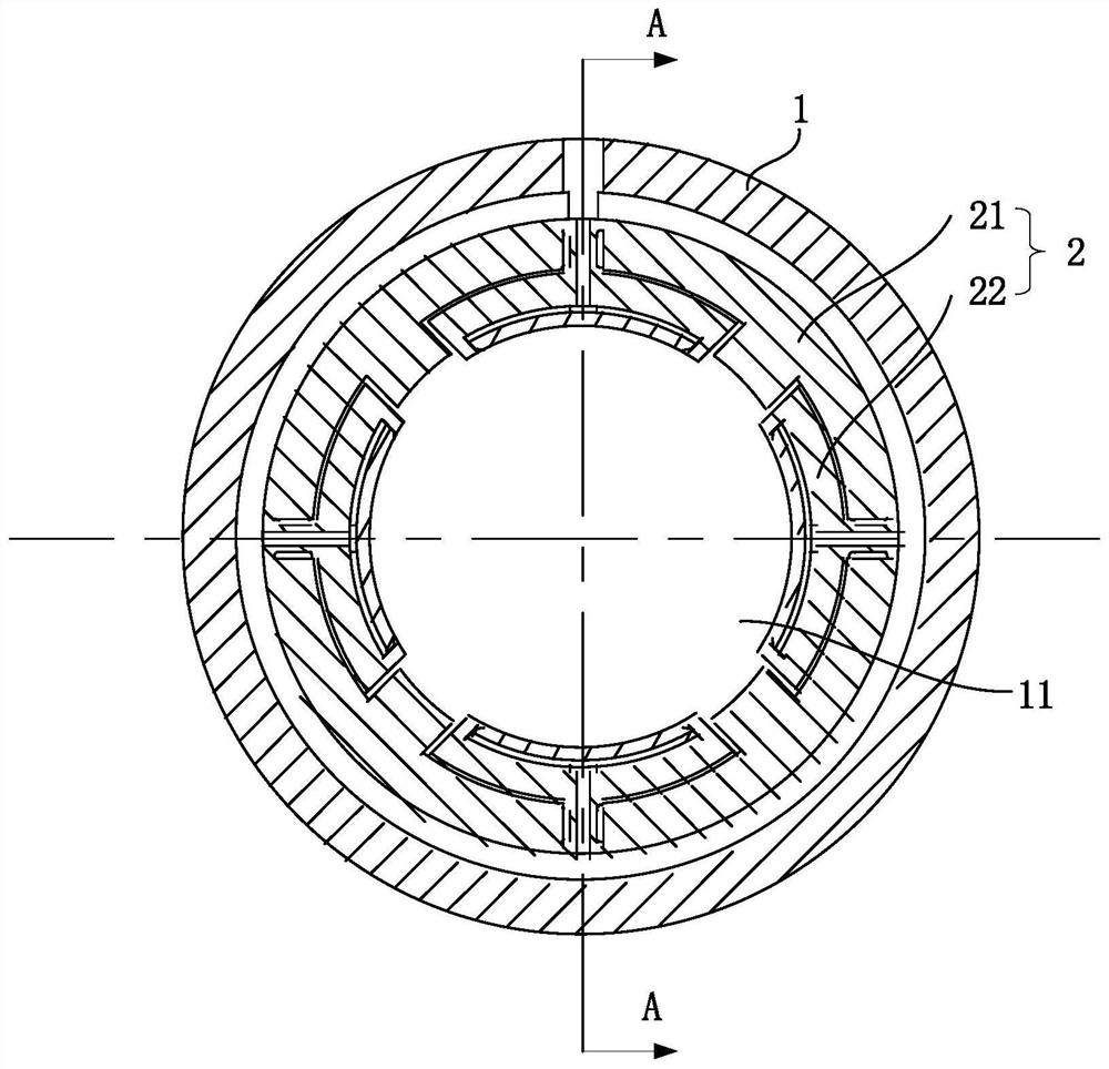
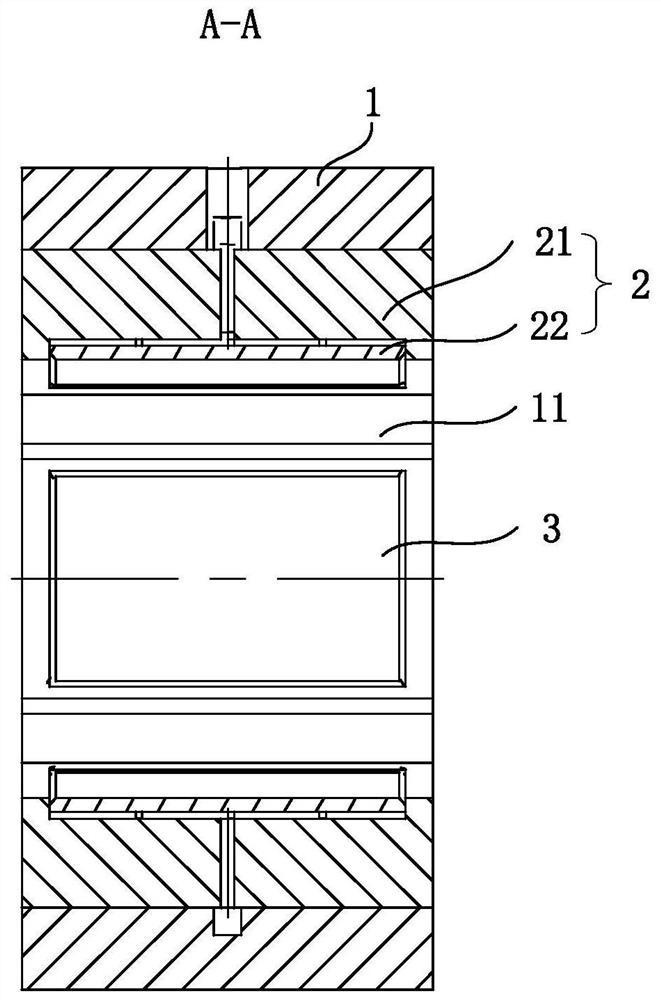
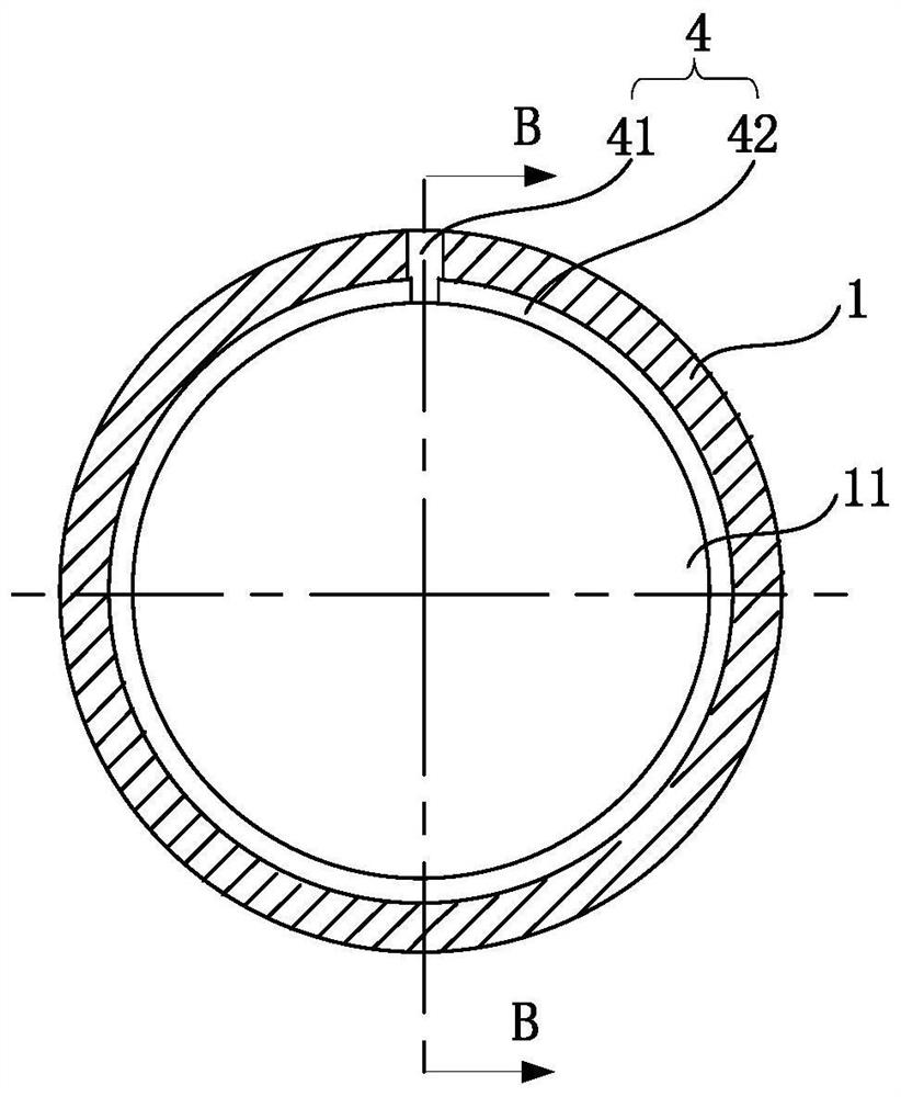
[0042] An embodiment of the present invention provides a radial bearing, including a bearing sleeve 1 , a bearing base 2 and a graphite part 3 . The bearing sleeve 1 includes a through hole 11 in which the rotating shaft 7 is mounted. The bearing base 2 includes a cylinder 21 mounted on the inner wall of the through hole 11 and a bearing bush 22 connected to the cylinder 21 through a connecting portion 23 . The connecting portion 23 is configured to enable the bearing bush 22 to move relative to the joint between the cylindrical body 21 and the bearing bush 22 under the action of an external force. The graphite component 3 is installed on the side of the bearing bush 22 away from the barrel 21 .

[0043] The radial bearing is used for installing the rotating shaft 7 . The bearing sleeve 1 is used for installing the bearing base 2, and the bear...


PUM


Abstract

The invention discloses a radial bearing and an air suspension centrifugal compressor, relates to the field of compressors, and aims to optimize the structure of the radial bearing. The radial bearing comprises a bearing sleeve, a bearing base and a graphite piece. The bearing sleeve comprises a through hole. The bearing base comprises a cylinder mounted on the inner wall of the through hole and a bearing bush connected with the cylinder through a connecting part. The connecting part is constructed to enable the bearing bush to move relative to the joint of the cylinder body and the bearing bush under the action of external force. The graphite piece is mounted on one side, away from the cylinder, of the bearing bush. According to the radial bearing provided by the technical scheme, due to the connection between the bearing bush and the base plate, the bearing bush cannot be separated from the base plate, and the bearing bush can incline to a certain degree relative to the base plate when being stressed in the working process of the radial bearing, so that the damping of the radial bearing can be adjusted, and the working requirement of the radial bearing is met.

Description

technical field [0001] The invention relates to the field of compressors, in particular to a radial bearing and an air suspension centrifugal compressor. Background technique [0002] The hydrostatic gas bearing is a rotor system that is supported by a pressure gas film between the bearing and the rotor, in which the gas enters the gap between the bearing and the rotor through small holes (laser micropores, porous pores) on the bearing surface , due to the small gap (0.02-0.05mm) between the rotor and the bearing, the gas will be squeezed after entering the gap, causing the pressure to rise, thereby supporting the rotor. Due to the small friction coefficient of gas, the static pressure gas bearing is a kind of bearing with basically no friction and low loss. [0003] Static pressure gas bearings are divided into single small hole throttling type, multi-small hole throttling type, micro groove throttling type, micropore throttling type, porous material throttling type static...

Claims


Application Information

Patent Timeline
Patent Type & Authority Applications(China)
IPC IPC(8): F16C32/06F16C33/16F04D29/057
CPCF04D29/057F16C32/0618F16C32/0622F16C32/0666F16C32/0685F16C33/16F16C2360/44
Inventor 张治平刘华陈玉辉钟瑞兴刘胜
Owner GREE ELECTRIC APPLIANCES INC
Why Eureka
Try Eureka