
Light-emitting diode and manufacturing method thereof

A technology of light-emitting diodes and manufacturing methods, which is applied in the direction of semiconductor devices, electrical components, circuits, etc., can solve the problems of insufficient expansion efficiency, poor antistatic ability, and insufficient brightness, so as to improve current congestion and reduce ESD explosion points , Improve the effect of antistatic ability

Active Publication Date: 2021-07-09
ANHUI SANAN OPTOELECTRONICS CO LTD
View PDF9 Cites 2 Cited by
  • Summary
  • Abstract
  • Description
  • Claims
  • Application Information

AI Technical Summary

Problems solved by technology

However, if the design of the finger extension is too short, the expected expansion effect will not be achieved, and the voltage will increase and the brightness will be insufficient; if the design of the finger extension is too long, since the end of the extension is closer to the N electrode, the current will preferentially flow from the The closer path expands, resulting in excessive current density around the end of the extension and the N electrode, and poor antistatic ability

Method used


Image

  • Light-emitting diode and manufacturing method thereof
  • Light-emitting diode and manufacturing method thereof
  • Light-emitting diode and manufacturing method thereof

Examples


Embodiment 1

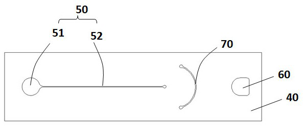
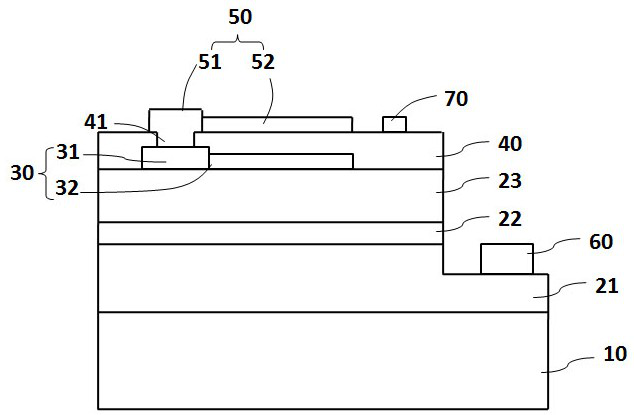
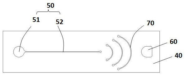
[0022] See attached figure 1 , the light-emitting diode disclosed in the present invention at least includes a substrate 10, a first conductivity type semiconductor layer 21, a light emitting layer 22, a second conductivity type semiconductor layer 23, and the first conductivity type semiconductor layer 21 and the second conductivity type semiconductor layer respectively Layer 23 electrically connects the first electrode 60 and the second electrode 50, wherein the second electrode 50 includes a pad portion 51 and an extension portion 52, and there is an extension portion between the end of the extension portion 52 and the first electrode 60 for expanding the current 70.

[0023] See attached figure 2 , wherein the material of the substrate 10 can be selected from Al 2 o 3 , SiC, GaAs, GaN, AlN, GaP, Si, ZnO, MnO any one or a combination of several. In this embodiment, a sapphire substrate 10 (sapphire substrate) is taken as an example, and the lattice direction may be (00...

Embodiment 2

[0040] In order to manufacture the above light-emitting diode, this embodiment provides a manufacturing method, the specific steps are as follows:

[0041] Step 1, providing a substrate 10, and sequentially depositing a first conductivity type semiconductor layer 21, a light emitting layer 22, and a second conductivity type semiconductor layer 23 on the surface of the substrate 10;

[0042] Step 2, making the first electrode 60 electrically connected to the first conductivity type semiconductor layer 21 and the second electrode 50 electrically connected to the second conductivity type semiconductor layer 23 respectively, wherein the second electrode 50 includes a pad portion 51 and extension 52;

[0043] Step 3, fabricate the extension part 70 for spreading the current on the surface of the second conductivity type semiconductor layer 23 between the end of the extension part 52 and the first electrode 60 .

[0044] In this embodiment, the step of depositing a transparent cond...


PUM


Abstract

The invention belongs to the field of semiconductors, and particularly relates to a light-emitting diode and a manufacturing method thereof, and the light-emitting diode at least comprises a substrate, a first conductive semiconductor layer, a light-emitting layer, a second conductive semiconductor layer, and a first electrode and a second electrode which are electrically connected with the first conductive semiconductor layer and the second conductive semiconductor layer respectively, the second electrode comprises a bonding pad part and an extension part, and is characterized in that an extension part for expanding current is arranged between the tail end of the extension part and the first electrode. The extension part can perform secondary extension on the current injected into the second electrode, and the current crowding phenomenon of a current dense area is improved, so that the antistatic capability of the light-emitting diode is improved, and ESD explosion points generated at the tail end of the extension part are reduced.

Description

technical field [0001] The invention belongs to the field of semiconductors, and in particular relates to a light emitting diode with an extension between a first electrode and a second electrode and a manufacturing method thereof. Background technique [0002] The conventional LED structure in the prior art includes: a substrate, an epitaxial layer on the substrate, a current blocking layer and a transparent conductive layer on the epitaxial layer, and P and N electrodes electrically connected to the epitaxial layer. In order to expand the current better to improve the brightness of the product, finger-like extensions are generally drawn out on the electrodes to optimize the current expansion. However, if the design of the finger extension is too short, the expected expansion effect will not be achieved, and the voltage will increase and the brightness will be insufficient; if the design of the finger extension is too long, since the end of the extension is closer to the N ...

Claims


Application Information

Patent Timeline
Patent Type & Authority Applications(China)
IPC IPC(8): H01L33/14H01L33/38H01L33/00
CPCH01L33/14H01L33/38H01L33/005
Inventor 毕东升徐胜娟徐凯蔡家豪黄照明张家豪
Owner ANHUI SANAN OPTOELECTRONICS CO LTD
Learn More