Heat dissipation device of CT detector and CT machine

A technology for a heat sink and a detector, which is applied in the fields of radiological diagnosis instruments, medical science, diagnosis, etc., can solve problems such as shortening the service life, affecting the use of CT, and detector imaging.

Active Publication Date: 2021-07-13
SHENZHEN ANKE HIGH TECH CO LTD
View PDF7 Cites 0 Cited by
  • Summary
  • Abstract
  • Description
  • Claims
  • Application Information

AI Technical Summary

Problems solved by technology

In order to miniaturize the size of the detector, it is necessary to place the power supply board and the DAS acquisition board perpendicular to the X-rays. In this way, lead blocks need to be installed on the detector module support to prevent the X-rays from irradiating the chips on the single board, thereby affecting Radiation damage to the chip shortens its lifespan and ultimately affects the use of the CT
There is light entering the detector from the air outlet of the casing, causing imaging problems of the detector; at the same time, the opening of the air outlet cannot effectively block X-rays from scattering out of the detector

Method used


Image

  • Heat dissipation device of CT detector and CT machine
  • Heat dissipation device of CT detector and CT machine
  • Heat dissipation device of CT detector and CT machine

Examples


Embodiment Construction

[0035] The following will clearly and completely describe the technical solutions in the embodiments of the present application with reference to the accompanying drawings in the embodiments of the present application. Obviously, the described embodiments are only some of the embodiments of the present application, not all of them. The components of the embodiments of the application generally described and illustrated in the figures herein may be arranged and designed in a variety of different configurations. Accordingly, the following detailed description of the embodiments of the application provided in the accompanying drawings is not intended to limit the scope of the claimed application, but merely represents selected embodiments of the application. Based on the embodiments of the present application, all other embodiments obtained by those skilled in the art without making creative efforts belong to the scope of protection of the present application.

[0036] In this ap...


PUM


Abstract

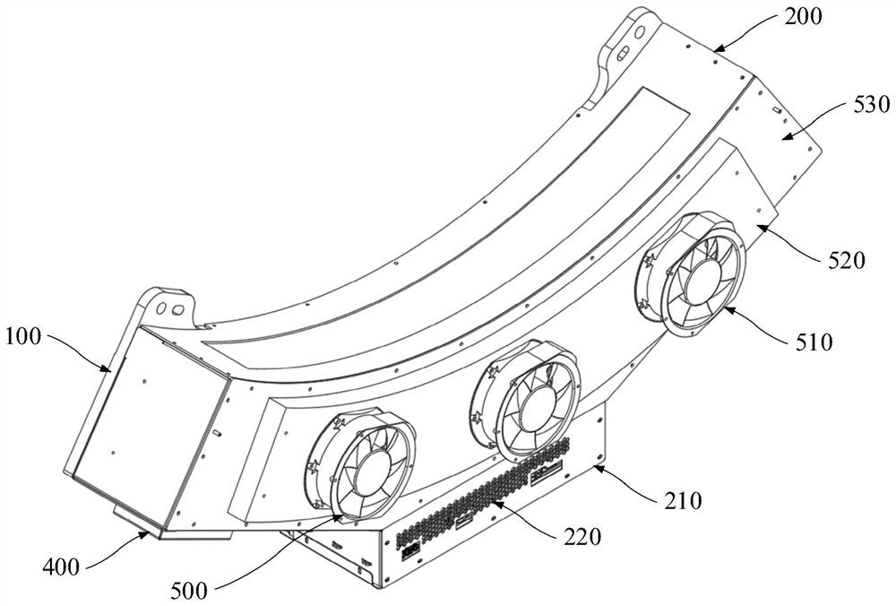
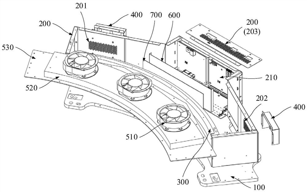
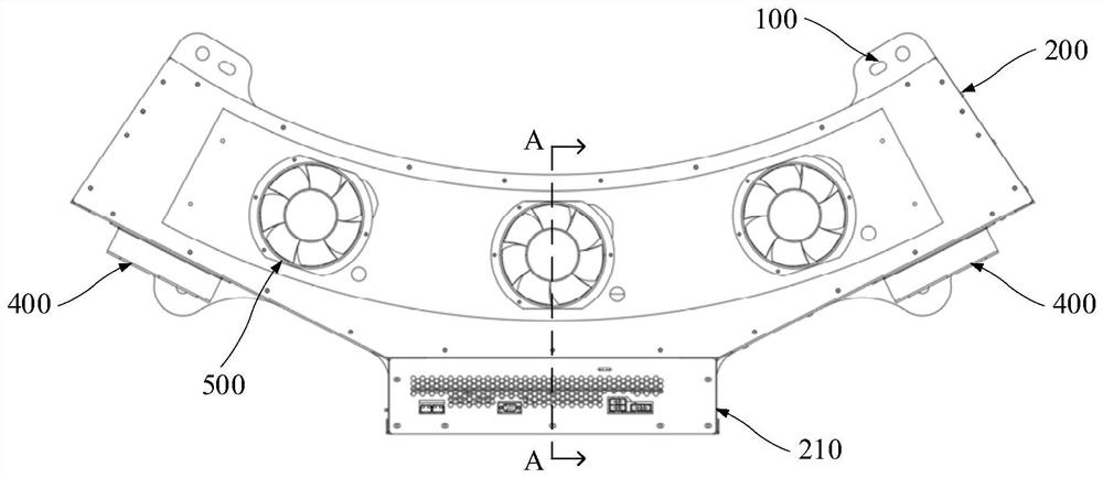
The embodiment of the invention provides a heat dissipation device of a CT detector and a CT machine, and relates to the technical field of device heat dissipation. The heat dissipation device of the CT detector comprises a base, a shell, a guide rail, an X-ray prevention structural part and a fan assembly. The shell is fixedly installed on the base, a circuit board installation groove and a plurality of air outlets are formed in the side face of the shell, and the base is fixedly installed on a rotor of the CT machine; the guide rail is mounted on the base, and the guide rail, the shell and the base form a closed structure; the X-ray preventing structural member is mounted on the air outlet of the shell; the fan assembly is installed on the shell. The heat dissipation device of the CT detector can realize the technical effect of X-ray protection on the basis of ensuring the heat dissipation efficiency.

Description

technical field [0001] The present application relates to the technical field of device heat dissipation, in particular, to a heat dissipation device for a CT detector and a CT machine. Background technique [0002] In the medical field, detectors such as CT (Computed Tomography) machines or PET (Positron Emission Computed Tomography, Positron Emission Computed Tomography) machines can detect the inside of the human body to check various indicators of the human body. Taking a CT machine as an example, it includes an X-ray tube assembly and a detector assembly. The detector assembly includes a detector that receives X-ray signals and electronic devices that process information read by X-rays, such as scintillators, photodiodes, And AD conversion devices, etc., and these devices will generate a lot of heat when they work, and the scintillator also needs to work at a relatively stable temperature. At this time, it is necessary to dissipate heat and control the temperature of th...

Claims


Application Information

Patent Timeline
IPC IPC(8): A61B6/03
CPCA61B6/032A61B6/035A61B6/4488
Inventor 朱寿礼刘卫琴
Owner SHENZHEN ANKE HIGH TECH CO LTD
Why Eureka
Try Eureka